Unit 2 · 16 min read
Assembling a Desktop PC, Step by Step
What the syllabus asks for 5
- Before you start
- Step-by-step build
- If it does not start
- Lab sign-off table
- Eight common assembly mistakes and how to avoid them
This unit is the lab manual for building a desktop computer from parts. Follow it in order, with the motherboard manual open beside you, and you will have a machine that reaches the BIOS screen on its first power-on.
- A complete assembly procedure from workspace preparation to first boot.
- Cable management and airflow.
- The meaning of beep codes and POST, and what to do if the PC does not start.
- A lab checklist and a sign-off table.
2.1 Before you start
- Clear a large bench; lay out anti-static mat; wear the wrist strap.
- Unbox parts and check against the list: case, PSU, motherboard, CPU, cooler, RAM, storage, GPU (optional), cables, screws, manuals.
- Read the motherboard manual: socket, RAM slot order, front-panel header layout.
- Keep the board on its box (a non-conductive surface) for the first steps; do not place it on the bag's outside, which can conduct.

2.2 Step-by-step build
Step 1: open the case. Remove both side panels. Note the pre-installed standoffs and the screws bag. If necessary, fit the I/O shield (backplate) into the rear cut-out, facing outwards (many boards have it built in).
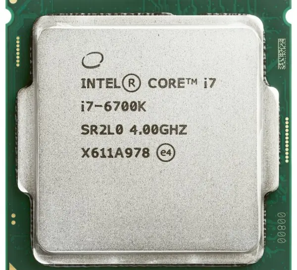
Step 2: install the CPU on the motherboard (outside the case is easier).
- Intel (LGA): lift the retention lever and plate; align the notches on the CPU edge with the socket; place the CPU gently (do not push, never touch the pins in the socket); lower the plate and lock the lever (the plastic cover pops off by itself).
- AMD AM4 (PGA): lift the lever; match the golden triangle on the CPU to the arrow on the socket; drop it in with no pressure; lower the lever. AM5 is LGA like Intel.
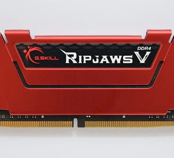
Step 3: install RAM. Open the slot clips; align the notch on the module with the key in the slot; press down evenly at both ends until the clips snap. For two modules use the slots the manual recommends (often A2 and B2) for dual channel.
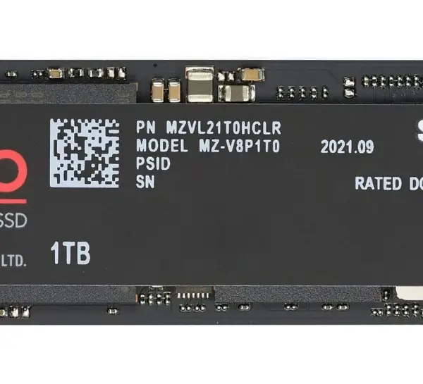
Step 4: M.2 SSD (if used). Remove the standoff screw, insert the SSD at about 30° into the M.2 socket, press down and fasten with the screw. Remove any protective film from the heatsink pad.
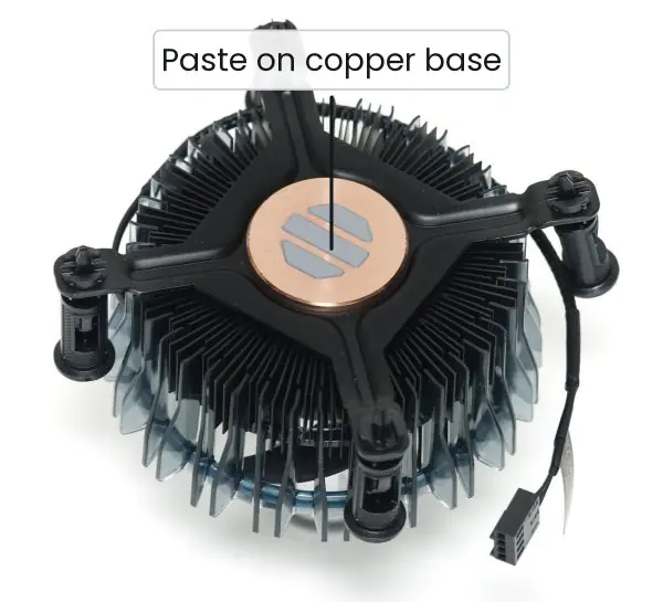
Step 5: cooler. If the cooler has pre-applied paste, remove the cover; otherwise apply a pea-sized dot of thermal paste in the centre of the CPU. Place the cooler vertically, tighten the screws diagonally in small turns, and connect the fan to the CPU_FAN header.
Step 6: mount the board in the case. Check the standoffs match the holes of your form factor (ATX, mATX, ITX) and that no extra standoff lies where there is no hole (a short circuit risk).
Lower the board, align with the I/O cut-out, and secure it with screws, tightening evenly but not over-tightening.
Step 7: PSU. Fit the PSU (fan facing the vent: down if the case has a bottom vent). Secure with four screws. Route cables behind the tray.
Step 8: connect power.
- 24-pin ATX to the board edge (the clip clicks).
- 8-pin (4+4) EPS CPU power near the CPU.
- SATA power to drives; PCIe power to the GPU.
Step 9: drives. Fasten the SSD/HDD in its bay or bracket; connect SATA data (L-shaped, keyed) to the board and SATA power from the PSU.
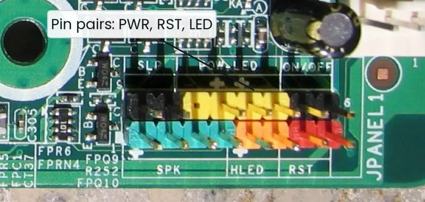
Step 10: front-panel connectors. The small header pins are the most error-prone step.
Check the manual diagram PWR_SW, RESET_SW, PWR_LED+/−, HDD_LED+/− (LEDs have polarity; switches do not), USB 3.0 (blue 19/20-pin), USB 2.0 (9-pin), HD_AUDIO (9-pin).
Step 11: graphics or expansion cards. Remove the slot cover, insert the card straight into the PCIe x16 slot until the latch clicks, screw it to the case, connect its power cables.
Step 12: tidy cables. Bundle cables with ties or Velcro behind the motherboard tray; keep them away from fans and out of the airflow path. Good airflow gives lower temperatures and less noise.
Step 13: final check before power. Nothing loose inside the case (a stray screw can short the board); CPU and case fans connected; all power connectors seated; RAM clicks closed; the monitor cable is plugged into the graphics card (if one is installed), not the board.
Step 14: first power-on. Connect monitor, keyboard, mouse and mains cable; switch on the PSU; press the case power button. Expect fans to spin, then the manufacturer logo and a prompt to enter BIOS/UEFI (usually Del or F2).
If you reach it, the build is successful. Check in BIOS that the CPU model, RAM size and the storage devices are detected, and watch the CPU temperature for a few minutes.
2.3 If it does not start
| Symptom | Likely cause and fix |
|---|---|
| Nothing happens, no fans | PSU switch off; mains cable; 24-pin or 8-pin not seated; power-button header wrong. Short the PWR_SW pins with a screwdriver to test |
| Fans spin, no display | monitor on the wrong port; GPU not seated or power missing; RAM not seated (reseat, try one stick); CPU power missing |
| Beep codes (AMI: one long + continuous short pattern) | AMI: 1 short = OK; continuous = memory or power fault; 1 long + 8 short = display adapter fault. Award: 1 long + 2 short = video error. Always check your board's manual, since codes vary |
| Debug LEDs (CPU / DRAM / VGA / BOOT) | the LED that stays lit points to the stage that failed |
| Restarts or shuts down after a short time | overheating: cooler not seated, no paste, fan not connected |
| "No boot device" | boot order, drive not detected (cable), no OS yet |
| USB or audio ports dead | front-panel header connected wrongly; check rear ports |
POST (power-on self-test) is the firmware checking the CPU, RAM, video and drives before handing over to the OS. Error codes or beeps during POST identify a failing component.
Troubleshooting method: reduce to the minimum (CPU, one RAM stick, board, PSU, GPU if needed), then add parts one at a time and test each.


2.4 Lab sign-off table
| # | Task | Done | Instructor |
|---|---|---|---|
| 1 | Use of wrist strap and workspace set-up | ||
| 2 | Identify all components by name and function | ||
| 3 | Install CPU, RAM and cooler on the board | ||
| 4 | Mount board and PSU in case | ||
| 5 | Connect power, drives, front panel correctly | ||
| 6 | Cable management completed | ||
| 7 | Power-on and BIOS detection of CPU, RAM, storage | ||
| 8 | Measure PSU rails with a multimeter (+12 V, +5 V, +3.3 V) |
PSU voltage check (multimeter). With the 24-pin connector plugged into the board and the PC on, probe the back of the connector: orange wire ≈ +3.3 V, red ≈ +5 V, yellow ≈ +12 V, with black as ground; acceptable tolerance is ±5 % (for +12 V: 11.4 to 12.6 V).
Green wire (PS_ON) shorted to black turns on a disconnected PSU (a paper-clip test, for a test only). Gray is Power Good, +5 V when the supply is stable; purple is +5 VSB standby.
2.5 Eight common assembly mistakes and how to avoid them
- Forgetting the I/O shield. The metal back plate must be fitted in the case before the board is screwed in. Without it the ports do not line up and the board must be removed again. Make it step 1 on your checklist.
- Extra or missing standoffs. A standoff under a place with no screw hole can touch the board and cause a short circuit. Fit standoffs only at the holes of your board's form factor. Count them before and after.
- Bent CPU pins or wrong CPU direction. Forcing a CPU into the socket bends pins or damages contacts. Match the corner marker and lower it gently; it should drop in with no pressure. Never touch the pins or contacts.
- Too much or no thermal paste. A pea-sized dot is enough; too much leaks onto the socket and no paste causes overheating. Remove the plastic film on a new cooler. Check that the cooler is tight and the fan cable is plugged into CPU_FAN.
- RAM not fully seated. A half-fitted DIMM gives a black screen and beep codes. Press until both side clips click, and use the slots in the order the manual shows for dual channel. Wrong slots only lose speed, but a loose stick stops the PC.
- Missing power connectors. The CPU needs the separate 4+4 or 8-pin cable besides the 24-pin cable, and a powerful GPU needs its own PCIe power cable. A PC with only the 24-pin connected often shows no sign of life. Trace every connector to the PSU.
- Front-panel wires on the wrong pins. Swapped power and reset pins make the button restart the PC, and reversed LED wires just stay dark. Read the pin map in the manual and fit the plugs one pair at a time. LEDs can be turned around safely, switches have no polarity.
- Poor cable management and airflow. Loose cables block fans and trap heat. Tie them behind the tray with cable ties and keep the front-to-back airflow free. A tidy case also makes later repairs far easier.
Formula and fact sheet
- Order: CPU → RAM → M.2 → cooler (outside) → board into case → PSU → cables → drives → front panel → cards → test.
- Thermal paste: pea-sized dot. Cooler screws: diagonal pattern.
- Power: 24-pin ATX, 8-pin EPS CPU, PCIe for GPU, SATA power for drives.
- Voltage colours: orange +3.3 V, red +5 V, yellow +12 V, black ground; tolerance ±5 %.
- Troubleshoot: minimum configuration, then add one part at a time.
Chapter summary
- Build in a fixed order, handling the CPU and RAM carefully and tightening screws evenly.
- Front-panel headers need the manual; LEDs have polarity, switches do not.
- Check twice before power-on: no loose screws, all power connected, monitor on the right port.
- If it fails, use beep codes, debug LEDs and a minimum-configuration test to isolate the part.
Practice
- Write the steps for installing a CPU and cooler and explain why thermal paste is needed.
- Why must you tighten cooler screws diagonally?
- A newly built PC shows no display although the fans spin. List five checks in order.
- What is dual channel and where do you place two RAM sticks?
- How do you identify the correct way to insert RAM, an Intel CPU and a SATA cable?
- Explain the purpose of the CPU_FAN header and the risk of not connecting it.
- List the connectors that come from the PSU and what each powers.
- What voltage should you read on the yellow wire of a healthy PSU? What is the acceptable range?
- Explain POST and how beep codes help.
- Explain why you should build with the minimum configuration first when the PC will not start.
Answers and worked solutions
1. Open the socket lever, align the notches (Intel) or triangle (AMD), place the CPU without pressure, lock the lever; add a pea-sized paste dot, seat the cooler, tighten diagonally, connect CPU_FAN. Paste fills microscopic air gaps between the CPU lid and cooler base, which would otherwise block heat transfer.
2. Even pressure prevents tilting that would crack the CPU or leave an air gap.
3. Monitor cable in the correct port (GPU vs board); monitor input source; reseat RAM; GPU seated and powered; CPU 8-pin power connected; try one RAM stick; clear CMOS.
4. Dual channel uses two modules on two memory channels for double bandwidth; place them in the slots recommended in the manual (often A2 and B2).
5. RAM has an off-centre notch matching the slot key; an Intel CPU has two notches matching the socket; a SATA connector is L-shaped and fits only one way.
6. It powers and monitors the CPU fan; without it the CPU overheats and the system may shut down or throttle.
7. 24-pin ATX: board; 4+4 EPS: CPU; PCIe 6+2: graphics card; SATA power: drives; Molex: older peripherals and fans.
8. +12 V, with a range of 11.4 to 12.6 V (±5 %).
9. POST is the firmware's hardware self-test at start-up; a failure produces beep patterns or debug codes that identify the faulty subsystem.
10. It removes variables: if the minimal system boots, add parts one at a time until the fault returns; the last part added is the culprit.
Model answers: medium (5 marks) and long (10 marks) questions
Q (5 marks). Explain how the CPU, cooler and RAM are installed on a motherboard.
These three parts are fitted to the board while it lies on its box outside the case, because there is more room (Plate 2.1).
CPU. Lift the socket lever (Intel LGA) or the retention arm (AMD AM4). Find the small triangle on one corner of the CPU and match it with the triangle on the socket.
Lower the CPU without pressure so that it sits flat, then close the plate and lever. Never touch the contacts, and never force it: a bent pin often cannot be repaired.
Cooler. Clean the CPU top, then place a pea-sized drop of thermal paste in the centre (a new cooler may already have paste, see Plate 2.1d).
Lower the cooler straight down, tighten the four screws or clips in a cross pattern and push the fan cable onto the CPU_FAN header.
RAM. Open the clips at both ends of the slot, match the notch of the DIMM to the key in the slot and press both ends down evenly until the clips snap shut. For dual channel use slots 2 and 4 (check the manual) when fitting two sticks.
| Part | Alignment aid | Final check |
|---|---|---|
| CPU | corner triangle | sits flat, lever closes easily |
| Cooler | four holes | tight; fan cable in CPU_FAN |
| RAM | single notch | both clips locked |
Q (10 marks). Describe the step-by-step procedure for assembling a desktop PC and explain how a first test (POST) is carried out. List four faults that can stop a new PC from starting.
Introduction. Assembly is a controlled sequence: build the core on the board, fix the board in the case, connect power and storage, then test before closing the case (Figure 2.1). Follow the manual of each part and an anti-static routine throughout.
Procedure.
- Prepare: clear the bench, wear the wrist strap, check all parts and screws against the list, and read the board manual.
- Case: remove both panels, fit the I/O shield and screw the standoffs that match the board.
- CPU, cooler and RAM: install them on the board as described above.
- M.2 SSD: fit it in its slot and fix it with the small screw.
- Board into case: lower it onto the standoffs and tighten all screws gently, without forcing.
- PSU and drives: fix the PSU, fit the 2.5 inch or 3.5 inch drives, and connect the SATA data and power cables.
- Power cables: plug in the 24-pin main and 4+4 pin CPU cables, then fit the graphics card and its PCIe power.
- Front panel: connect the power switch, reset switch, LED and USB/audio cables using the pin map (Plate 2.2).
- Test (POST): connect monitor, keyboard and mains, and press power. Fans spin and the board runs the Power-On Self-Test, which checks the CPU, RAM and graphics. One short beep or a logo means success; other beeps or a debug code point to a fault.
- Close up: switch off, tidy the cables, close the panels and start the OS installation.
Faults that stop a new PC. (1) No power: mains, PSU switch or 24-pin not seated. (2) Fans spin but no display: RAM not seated or cable in the wrong output. (3) Repeated beeps: RAM or graphics fault.
(4) Power then shutdown: cooler not fitted properly, or a short circuit from a stray standoff.
| POST result | Meaning | Action |
|---|---|---|
| Nothing at all | no power | check PSU, 24-pin, PWR pins |
| 1 short beep | pass (most boards) | enter BIOS, install OS |
| Continuous beeps | RAM or power fault | reseat RAM |
| Long + short beeps | graphics fault | reseat card, check cable |
Conclusion. Methodical assembly with a test of the minimum system first finds a fault in minutes rather than hours. A written checklist, signed at each step, is the mark of a professional technician.