Unit 3 · 12 teaching hours · 50 min read
The Data Link Layer and LANs
What the syllabus asks for 10
- Services of the data link layer
- Framing
- Error detection
- Error correction: Hamming codes
- Flow control and error control
- HDLC and PPP
- Multiple access protocols
- Ethernet
- Wireless LAN (IEEE 802.11)
- Seeing the ideas: frames, checks, windows and shared media
The physical layer delivers bits, but it delivers them with errors and without any notion of where one message ends and the next begins.
The data link layer repairs that on a single link: it cuts the bit stream into frames, adds a check so that damage can be detected, and (when the link is shared) decides who may transmit.
This is the unit where you will do real arithmetic with binary polynomials, Hamming codes and sliding windows, so every number below was recomputed by bca/tools/check_networking.py.
- Framing: byte stuffing and bit stuffing.
- Error detection: parity, checksum, CRC; error correction: Hamming codes.
- Flow and error control: stop-and-wait, Go-Back-N and Selective Repeat.
- HDLC and PPP.
- Medium access: ALOHA, CSMA, CSMA/CD, Ethernet frames and switching, VLANs, Wi-Fi CSMA/CA.
3.1 Services of the data link layer
The layer provides framing, physical (MAC) addressing, error control (detect and perhaps correct or retransmit), flow control (do not overrun the receiver) and, on shared media, medium access control.
On a LAN the layer is split into two sublayers: LLC (logical link control, IEEE 802.2: multiplexing of network protocols, optional flow control) and MAC (medium access control: addresses and access method).
The service can be unacknowledged connectionless (Ethernet), acknowledged connectionless or acknowledged connection-oriented (HDLC).
3.2 Framing
The receiver needs to know where a frame starts and ends. Counting characters is fragile (a single damaged count destroys synchronisation), so real protocols use flags.
Byte stuffing
A flag byte (7E in hexadecimal for PPP) marks the frame boundary. If the data contains 7E or the escape byte 7D, the sender inserts an escape byte 7D before it; the receiver removes the escapes. In PPP the escaped byte is also XORed with 20, so a data 7E becomes 7D 5E.
Bit stuffing
HDLC uses the flag 01111110. To keep that pattern out of the data, the sender inserts a 0 after every run of five consecutive 1s in the data; the receiver deletes a 0 that follows five 1s.
For the data 0111111011111011111 the sender transmits 0111110101111100111110 (three zeros inserted, each after a run of five 1s; the run counter restarts after each insertion). The receiver reverses it and recovers the original.
The expansion is at most one bit in five, worst case 20 %, usually far less.
The count of 1s restarts after an inserted 0, and a run of six or more ones becomes five ones, a stuffed zero, then the rest. Simply replacing every "11111" by "111110" gives wrong answers for long runs, because the stuffed zero changes the next run.
3.3 Error detection
Bits get damaged by noise, either as single-bit errors or burst errors (a run of damaged bits; the burst length is measured from the first to the last damaged bit).
At high data rates a burst touches more bits than at low rates, so bursts are more common than isolated errors.
Parity and two-dimensional parity
A parity bit makes the number of 1s even (even parity) or odd. It detects every odd number of bit errors and misses every even number, so it catches only 50 % of random damage.
Two-dimensional parity arranges data in rows and adds a parity bit per row and per column; it detects all single, double and triple errors and can correct a single-bit error (the wrong row and the wrong column intersect at the bad bit).
Internet checksum
Used by IP, ICMP, UDP and TCP. Treat the data as 16-bit words, add them with end-around carry (any carry out of bit 16 is added back at the low end), and transmit the one's complement of the sum.
The receiver adds all words including the checksum; the result must be 0xFFFF.
A 20-byte header holds the words 4500 0073 0000 4000 4011 (checksum field 0000) C0A8 0001 C0A8 00C7. The sum with end-around carry is 0x479E, whose complement is B861; that value goes in the checksum field.
A receiver that adds the ten words plus B861 obtains FFFF and accepts the header.
The checksum is weak (it cannot see reordered 16-bit words, for instance) but cheap to compute in software.
Cyclic redundancy check (CRC)
CRC treats the bit string as the coefficients of a polynomial over GF(2) (arithmetic where addition and subtraction are both XOR). Sender and receiver agree on a generator polynomial G(x) of degree r (r + 1 bits). To send message M:
- Append r zeros to M.
- Divide the result by G using XOR long division; the remainder has r bits.
- Replace the appended zeros by the remainder. The transmitted frame T is exactly divisible by G.
The receiver divides the received bits by G; a non-zero remainder means errors.
Message 1101011011, r = 4. Append four zeros: 11010110110000. XOR division by 10011 leaves the remainder 1110. The transmitted frame is 11010110111110. The receiver's division of that frame gives 0000, accepting it.
If bit 4 is flipped in transit, the receiver's remainder becomes 0111, which is non-zero, so the error is detected.
Append three zeros: 100100000. Divide by 1101 step by step (only the leading 1 positions are XORed):
| Step | Working register after XOR |
|---|---|
| bit 0 | 010000000 |
| bit 1 | 001010000 |
| bit 2 | 000111000 |
| bit 3 | 000001100 |
| bit 5 | 000000001 |
The last three bits 001 are the remainder, so the frame is 100100001.
A CRC with a generator of degree r detects every single-bit error (if G has at least two terms), every double-bit error within a suitable length, every odd number of errors if (x + 1) divides G, every burst of length ≤ r, and a burst of length r + 1 with probability 1 − 2^−(r−1).
Standard generators: CRC-16-CCITT x¹⁶ + x¹² + x⁵ + 1, and CRC-32 used by Ethernet and Wi-Fi (x³² + x²⁶ + … + 1).
The standard check values for the ASCII string "123456789" are 0x29B1 for CRC-16/CCITT-FALSE and 0xCBF43926 for CRC-32; the program at the end of the unit reproduces both.
CRC is computed in hardware by a shift register with XOR gates at the positions of the 1s in G.
3.4 Error correction: Hamming codes
A code with minimum Hamming distance d between any two valid codewords can detect d − 1 errors and correct ⌊(d − 1)/2⌋ errors. The classic Hamming code puts parity bits at the power-of-two positions 1, 2, 4, 8, … and data in the others.
For m data bits we need r parity bits with 2^{r} ≥ m + r + 1: 4 data bits need r = 3 (the (7,4) code), 8 data bits need r = 4 (the (12,8) code), 11 data bits need r = 4 (the (15,11) code).
Parity bit at position 2^{k} covers every position whose binary representation has bit k set.
Positions 1…7: p1 p2 d3 p4 d5 d6 d7 with data bits d3 = 1, d5 = 0, d6 = 1, d7 = 1.
- p1 covers positions 1, 3, 5, 7: d3 ⊕ d5 ⊕ d7 = 1 ⊕ 0 ⊕ 1 = 0, so p1 = 0.
- p2 covers 2, 3, 6, 7: 1 ⊕ 1 ⊕ 1 = 1, so p2 = 1.
- p4 covers 4, 5, 6, 7: 0 ⊕ 1 ⊕ 1 = 0, so p4 = 0.
Codeword: 0110011. Suppose position 5 arrives flipped (0110111). The receiver recomputes the checks: the three checks give the binary number (p4 p2 p1) = 101 = 5, the syndrome, which is the position of the bad bit. Flip it back and the word is repaired.
For the 8-bit data 10011010, r = 4 and the codeword is 011100101010.
The (7,4) Hamming code has minimum distance 3 (verified by comparing all 120 pairs of the 16 codewords), so it corrects any single-bit error or detects any two-bit error but not both; an extended Hamming code adds an overall parity bit to reach distance 4 (single-error correction and double-error detection, used in ECC memory).
Correction (forward error correction) is better when retransmission is costly or impossible (deep-space, broadcast, flash storage). Detection plus retransmission (ARQ) needs far fewer check bits and is the choice on reliable, short-delay links such as LANs.
3.5 Flow control and error control
Flow control stops a fast sender swamping a slow receiver. Error control repairs damage using ARQ (Automatic Repeat reQuest): the receiver acknowledges good frames and the sender retransmits on a timeout or on a negative acknowledgement.
Stop-and-wait
Send one frame, wait for its acknowledgement, send the next. Let the frame take t_f seconds to transmit and the one-way propagation be t_p. One cycle costs t_f + 2 t_p, so utilisation U = t_f / (t_f + 2 t_p).
With t_f = 12 ms and t_p = 20 ms: U = 12 / 52 = 0.2308, only 23 % of the link capacity. The sender is mostly idle waiting. Loss recovery uses a timeout and a 1-bit sequence number (0, 1) so that a duplicated frame is recognised.
Sliding window
The sender may have up to W unacknowledged frames in flight. U = min(1, W t_f / (t_f + 2 t_p)).
The minimum window for full utilisation is W ≥ 1 + 2 t_p / t_f = 1 + 40 / 12, so W = 5 frames in the example above (the formula (t_f + 2 t_p)/t_f = 52/12 = 4.33 is rounded up).
With sequence numbers of k bits the Go-Back-N window can be at most 2^{k} − 1 and the Selective Repeat window at most 2^{k-1}; 7 frames in flight need 3 bits for Go-Back-N and a Selective Repeat window of 4 needs 3 bits of sequence number.
Go-Back-N (GBN)
The receiver accepts frames only in order and sends cumulative acknowledgements; a damaged or missing frame makes it discard everything after it. When the timer for the oldest frame expires, the sender goes back and resends that frame and all that followed it.
Selective Repeat (SR)
The receiver buffers out-of-order frames and acknowledges each one individually; the sender retransmits only the frame whose timer expired. It wastes less bandwidth when errors are frequent, at the cost of buffers and complexity.
Idealised: the sender transmits in rounds of up to four frames. Go-Back-N transmits 0 1 2 3; frame 2 is lost so frame 3 is discarded.
After the timeout it resends 2 3 4 5, then 6 7 8 9: the transmissions are 0 1 2 3 2 3 4 5 6 7 8 9, 12 in all for 10 frames. Selective Repeat transmits frame 2 once more but never repeats frame 3, so it needs 11.
The difference grows with the window size and with the loss rate.
Piggybacking places the acknowledgement for received data inside a frame travelling the other way. A NAK or selective acknowledgement can ask for a specific frame at once without waiting for a timer.
3.6 HDLC and PPP
HDLC (High-level Data Link Control) is a bit-oriented protocol with the frame: flag 01111110 | address (8 bits) | control (8 or 16 bits) | data | FCS (16- or 32-bit CRC) | flag.
The control field distinguishes three frame types: I-frames (information, carrying send and receive sequence numbers N(S), N(R) and a poll/final bit), S-frames (supervisory: RR receive-ready, RNR receive-not-ready, REJ go-back-N, SREJ selective reject) and U-frames (unnumbered: link set-up and disconnect, SABM, DISC, UA). HDLC uses bit stuffing.
PPP (Point-to-Point Protocol), the successor of SLIP, links two nodes over dial-up, DSL (PPPoE) or leased lines. A PPP frame is flag 7E | address FF | control 03 | protocol | payload | FCS | flag, with byte stuffing.
Its phases are: dead → establish (LCP negotiates link options) → authenticate (PAP sends the password in clear, CHAP proves knowledge of a secret using a challenge and a hash) → network (an NCP, for example IPCP, assigns the IP address) → open → terminate.
An ISP broadband connection in Nepal that asks you for a username and password is typically PPPoE using PAP or CHAP.
3.7 Multiple access protocols
When many stations share a medium, a multiple access protocol decides who may transmit. The families are: random access (ALOHA, CSMA), controlled access (polling, token passing, reservation) and channelisation (FDMA, TDMA, CDMA).
ALOHA
In pure ALOHA a station sends whenever it has a frame; if no acknowledgement arrives it waits a random time and resends.
A frame is vulnerable for two frame-times (any other transmission starting one frame-time before or after overlaps it).
With G the average number of frame attempts per frame time (offered load), the throughput is S = G e^{-2G}, maximal at G = 0.5 with S = 1/(2e) = 0.1839.
In slotted ALOHA stations may start only at slot boundaries, the vulnerable period is one slot, S = G e^{-G}, maximal at G = 1 with S = 1/e = 0.3679: slotting doubles the best throughput.
Beyond the peak, more offered load reduces throughput because collisions dominate (pure ALOHA at G = 1 gives only 0.1353).
CSMA family
Carrier sense multiple access listens before transmitting.
1-persistent CSMA transmits immediately when the medium is idle (and keeps listening when busy); non-persistent waits a random time when busy; p-persistent (slotted channels) transmits with probability p. Collisions still occur because of propagation delay: two stations may both sense idle before the other's signal arrives.
CSMA/CD (classic Ethernet)
Add collision detection: a station listens while it transmits, and if the signal on the wire differs from what it sent, it stops, sends a short jam signal and waits using binary exponential backoff: after the k-th collision choose a random integer from 0 … 2^min(k,10) − 1 and wait that many slot times (51.2 µs at 10 Mbps); give up after 16 attempts.
After the third collision the longest wait is (2³ − 1) × 51.2 = 358.4 µs; after the tenth it is (2¹⁰ − 1) × 51.2 = 52,377.6 µs.
For a collision to be detected before the sender finishes, the frame transmission time must be at least the round-trip propagation: t_frame ≥ 2 t_prop.
At 10 Mbps the slot time is 51.2 µs, which is 512 bits, so the minimum Ethernet frame is 512 bits = 64 bytes. At 100 Mbps the same 512 bits last 5.12 µs, so the collision-domain diameter shrinks to about a tenth.
The efficiency of CSMA/CD is approximately 1 / (1 + 5a), where a = t_prop / t_frame; with a = 0.1 it is 0.667.
CSMA/CA (Wi-Fi)
Radio cannot listen while transmitting, so Wi-Fi avoids collisions.
A station waits for an idle medium for a DIFS (34 µs in 802.11a/g/n with 9 µs slots and 16 µs SIFS: DIFS = SIFS + 2 × slot), then counts down a random backoff; the receiver answers with an acknowledgement after a SIFS, which has priority.
Optionally an RTS/CTS handshake reserves the channel and solves the hidden-station problem (two stations that cannot hear each other both transmit to the same access point).
The exposed-station problem is the mirror case in which a station refrains from a harmless transmission.
Controlled access
Polling: a primary asks each secondary in turn. Token passing: a token circulates (token ring, FDDI); only the holder sends. They guarantee a bounded delay, which random access cannot.
3.8 Ethernet
Ethernet (IEEE 802.3) is the dominant LAN. Speeds: 10 Mbps (10BASE-T), 100 Mbps (Fast Ethernet), 1 Gbps, 10 Gbps and beyond.
| Field | Size | Purpose |
|---|---|---|
| Preamble | 7 bytes (10101010 …) | clock synchronisation |
| Start frame delimiter | 1 byte (10101011) | marks the start |
| Destination MAC | 6 bytes | receiver |
| Source MAC | 6 bytes | sender |
| Type / length | 2 bytes | upper protocol (0x0800 IPv4, 0x86DD IPv6, 0x0806 ARP) |
| Data | 46–1500 bytes (padded to 46) | payload; the MTU is 1500 |
| FCS | 4 bytes | CRC-32 |
The frame is 64–1518 bytes (excluding preamble).
A MAC address is 48 bits written in hex such as 00:1A:2B:3C:4D:5E; the first 24 bits are the vendor (OUI), the least significant bit of the first byte marks multicast, and FF:FF:FF:FF:FF:FF is broadcast.
Including the preamble, SFD and the 12-byte inter-frame gap, a full 1500-byte frame uses 7 + 1 + 14 + 1500 + 4 + 12 = 1538 byte times on the wire, so the best throughput efficiency for payload is 1500 / 1538 = 0.9753.
Switches
A switch operates at layer 2.
It builds a MAC address table by learning: when a frame arrives on port p with source address S, record S → p. For a destination in the table it forwards to that port only (and filters if it is the arrival port); for an unknown destination or the broadcast address it floods to all ports except the arrival port.
Table entries expire after about five minutes.
Switching modes: store-and-forward (check the CRC before forwarding), cut-through (forward after reading the destination address, lower delay, no error filtering), fragment-free (wait for 64 bytes).
Hosts A, B, C on ports 1, 2, 3 of an empty switch. A → B: unknown destination, flood to 2 and 3; the switch learns A = 1. B → A: A is known, send only to port 1; learns B = 2. A → B again: now only port 2. C never sees the A–B conversation after the first frame.
Spanning tree and VLANs
Redundant switch links create loops, and since Ethernet frames carry no hop count, a broadcast circulates forever (a broadcast storm).
STP (IEEE 802.1D) elects a root bridge (lowest bridge ID) and blocks the redundant ports, giving a loop-free tree; RSTP converges in seconds instead of tens of seconds.
A VLAN (802.1Q) divides one switch into several logical LANs, each its own broadcast domain, by adding a 4-byte tag carrying a 12-bit VLAN ID (up to 4094 VLANs).
A trunk port carries tagged frames of many VLANs between switches; traffic between VLANs needs a router (or a layer-3 switch).
Address resolution
To send an IP packet to a neighbour on the same LAN, a host needs its MAC address. ARP broadcasts "who has 192.168.1.1?" and the owner replies unicast with its MAC; the answer is cached for a few minutes.
The ARP request is a frame with destination FF:FF:FF:FF:FF:FF and Ethernet type 0x0806.
3.9 Wireless LAN (IEEE 802.11)
A Wi-Fi network is an infrastructure BSS (stations plus an access point) or an ad hoc (IBSS) network. The access point's name is the SSID.
A station scans (passive: listens for beacons; active: sends probe requests), authenticates and associates. Frames have up to four address fields because a frame may pass through an AP between a station and a wired host.
Standards: 802.11b (2.4 GHz, 11 Mbps), a (5 GHz, 54 Mbps), g (2.4 GHz, 54), n (MIMO, 600), ac (5 GHz, multi-gigabit), ax (Wi-Fi 6, OFDMA). Security: WPA2 (AES-CCMP, pre-shared key or 802.1X) and WPA3; WEP is broken and must not be used.
Practising the commands
This program computes the CRC examples, the CRC-16 and CRC-32 check values, the Hamming code and the bit stuffing of this unit.
import zlib
def xor_div(dividend, poly):
    d = list(dividend); n = len(poly)
    for i in range(len(d) - n + 1):
        if d[i] == "1":
            for j in range(n): d[i + j] = "0" if d[i + j] == poly[j] else "1"
    return "".join(d[-(n - 1):])
def crc_send(msg, poly):
    r = xor_div(msg + "0" * (len(poly) - 1), poly); return msg + r, r
frame, rem = crc_send("1101011011", "10011"); print(frame, rem, xor_div(frame, "10011"))
frame2, rem2 = crc_send("100100", "1101"); print(frame2, rem2)
bad = list(frame); bad[3] = "1" if bad[3] == "0" else "0"; print("corrupted remainder", xor_div("".join(bad), "10011"))
def crc16(data, poly=0x1021, crc=0xFFFF):
    for byte in data:
        crc ^= byte << 8
        for _ in range(8): crc = ((crc << 1) ^ poly) & 0xFFFF if crc & 0x8000 else (crc << 1) & 0xFFFF
    return crc
print("CRC-16/CCITT-FALSE %04X" % crc16(b"123456789"), "CRC-32 %08X" % zlib.crc32(b"123456789"))
def bit_stuff(s):
    out, run = [], 0
    for b in s:
        out.append(b); run = run + 1 if b == "1" else 0
        if run == 5: out.append("0"); run = 0
    return "".join(out)
print(bit_stuff("0111111011111011111"))
11010110111110 1110 0000
100100001 001
corrupted remainder 0111
CRC-16/CCITT-FALSE 29B1 CRC-32 CBF43926
0111110101111100111110
A second program covers the Hamming code and the checksum:
def hamming_encode(data):
    m = len(data); r = 0
    while 2 ** r < m + r + 1: r += 1
    n = m + r; code = [0] * (n + 1); j = 0
    for i in range(1, n + 1):
        if i & (i - 1): code[i] = int(data[j]); j += 1
    for p in range(r):
        pos = 2 ** p
        code[pos] = sum(code[i] for i in range(1, n + 1) if i & pos and i != pos) % 2
    return "".join(map(str, code[1:]))
def syndrome(word):
    s = 0
    for i, b in enumerate(word, 1):
        if b == "1": s ^= i
    return s
w = hamming_encode("1011"); print(w, syndrome(w))
bad = list(w); bad[4] = "1" if bad[4] == "0" else "0"; print("".join(bad), "syndrome", syndrome("".join(bad)))
print(hamming_encode("10011010"))
def inet_checksum(words):
    s = sum(words)
    while s >> 16: s = (s & 0xFFFF) + (s >> 16)
    return ~s & 0xFFFF
hdr = [0x4500, 0x0073, 0x0000, 0x4000, 0x4011, 0x0000, 0xC0A8, 0x0001, 0xC0A8, 0x00C7]
print("%04X" % inet_checksum(hdr))
0110011 0
0110111 syndrome 5
011100101010
B861
3.10 Seeing the ideas: frames, checks, windows and shared media
The data link layer is where a raw bit stream becomes a trustworthy sequence of frames.
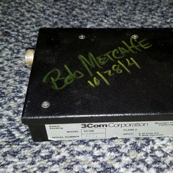
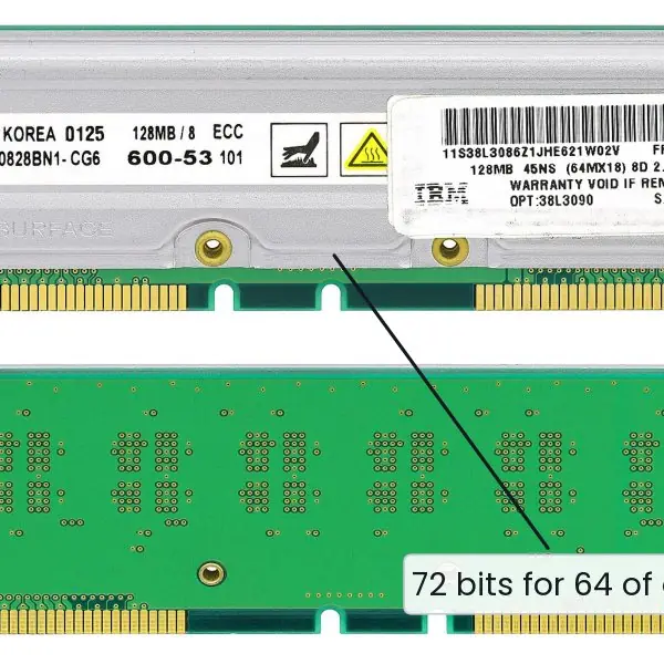
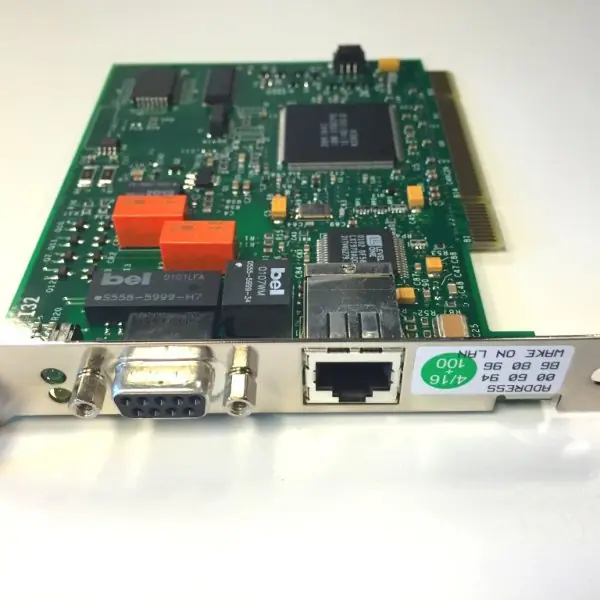
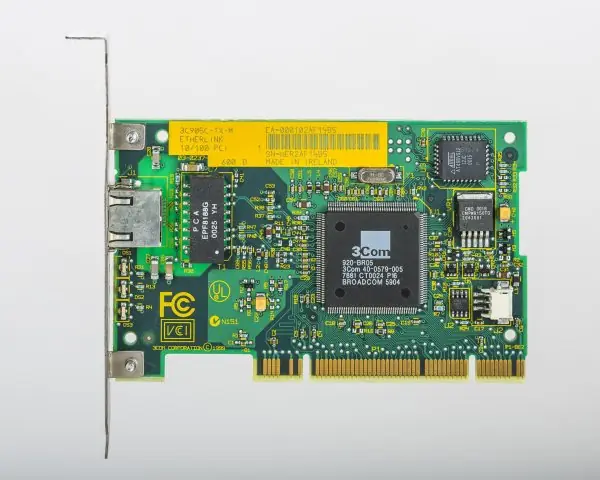
Plate 3.1 shows the history and the hardware of that idea: an early Ethernet transceiver signed by its inventor, the plaque of ALOHAnet (the radio network from which Ethernet's random access grew), a memory module that corrects its own errors with a Hamming-type code, and a token-ring adapter, the controlled-access rival that lost.
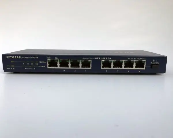
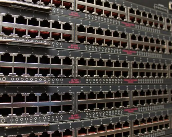
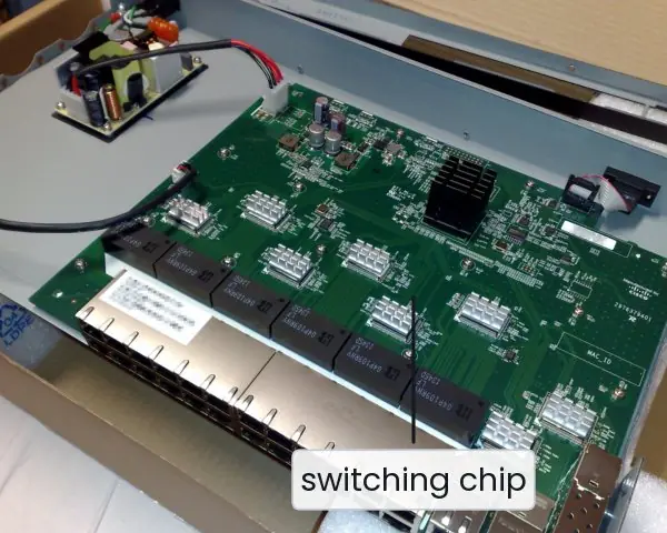
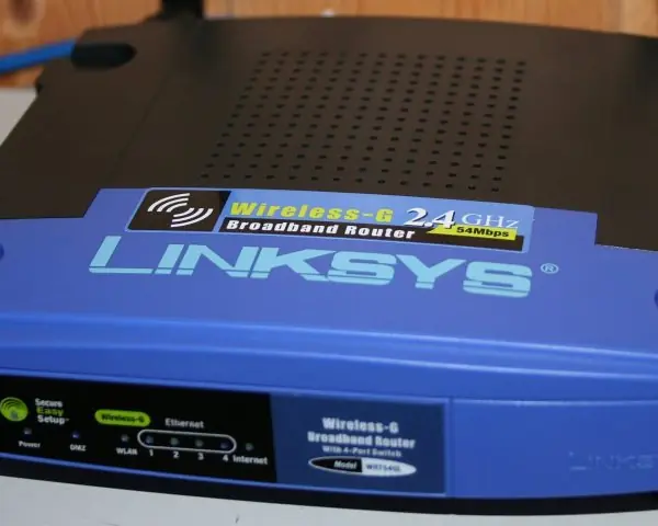
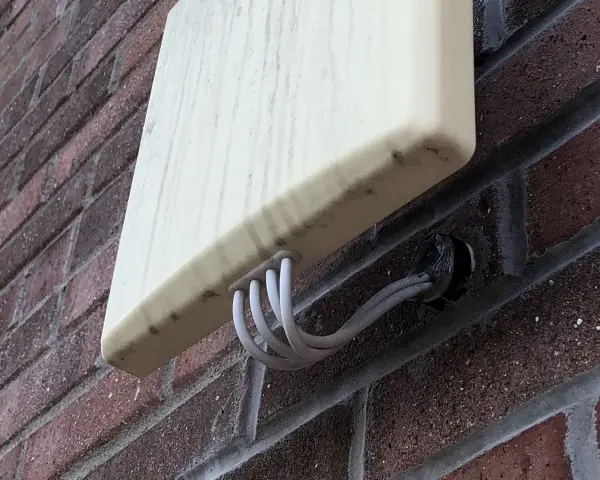
Plate 3.2 shows the boxes that connect a LAN, from the hub (one shared wire) to the switch (one private wire per host). Plate 3.3 shows the wireless side.
Figures 3.1 to 3.12 then run the unit's calculations on real bit patterns: stuffing, the CRC division, the Internet checksum, a Hamming code, window protocols, ALOHA, backoff, the Ethernet frame, switch learning, Wi-Fi timing, spanning tree and VLAN tags.



3.10.1 Eight uses of data link technology in Nepal
- Ethernet in colleges and offices. Almost every computer lab, bank branch and government office in Nepal is wired with Ethernet over Cat5e or Cat6 to a switch. The Ethernet frame (Fig. 3.9) and its CRC-32 check mean a damaged frame is discarded before the user ever sees it. A switch with one private wire per host (Plate 3.2b) gives each computer its full speed.
- Wi-Fi in homes, hostels and cafes. A home router (Plate 3.3a) gives a family one access point shared by phones, laptops and televisions. Because radio cannot detect collisions, every device follows the CSMA/CA waiting rules (Fig. 3.11), so a crowded cafe network slows down when many devices contend. Placing the router centrally and choosing a free channel reduces the contention.
- PPPoE login with an ISP. Many home broadband lines ask the router for a username and password. This is PPP over Ethernet, and PAP or CHAP checks the secret before the ISP's equipment assigns an IP address. Knowing the PPP phases explains why a wrong password gives no IP address at all.
- VLANs on a campus. A college can keep the administration, the teachers' offices and the student labs on separate VLANs (Fig. 3.12), although they share the same switches. A student's computer then cannot reach the accounts server directly, and a broadcast storm in one lab does not slow another. The tag adds only 4 bytes to each frame.
- Loop protection in hospitals and banks. A hospital or head office joins its switches in a ring so that one cable cut does not cut off a ward or a floor. Spanning tree blocks the redundant link until it is needed (Fig. 3.12), which prevents broadcast storms. After a cable failure the blocked port opens within seconds with RSTP.
- ECC memory in data centres. The servers behind ConnectIPS, Fonepay and the banks' systems use memory with an error-correcting code (Plate 3.1c). Eight extra bits protect every 64 data bits, so a flipped bit caused by cosmic rays is corrected silently (Fig. 3.4). One undetected flipped bit in an account balance would be far more costly than a few extra chips.
- Error control in mobile and satellite links. A mobile phone's radio link repeats damaged blocks with a retransmission protocol (ARQ) and adds forward error correction for the hardest conditions. A window protocol keeps a long, slow link full (Figs. 3.5 and 3.6). This is why a download keeps going when the signal flickers in a hill road.
- Controlled access in industry and old systems. Polling and token passing give a guaranteed worst-case delay, which random access cannot (Plate 3.1d). Some factory control networks and metering systems still use polling for this reason. CSMA/CD and ALOHA (Fig. 3.7) are the right choice when traffic is bursty and delay is not critical, as in an office.
Formula and fact sheet
- Hamming: 2^{r} ≥ m + r + 1; parity bits at positions 1, 2, 4, 8; syndrome = position of the error. Distance d detects d − 1 and corrects ⌊(d − 1)/2⌋ errors.
- CRC: append r zeros, divide (XOR) by the generator, append the remainder; receiver remainder 0 means accepted. Detects every burst of length ≤ r.
- Stop-and-wait U = t_f / (t_f + 2 t_p); sliding window U = min(1, W t_f / (t_f + 2 t_p)). GBN window ≤ 2^{k} − 1, SR window ≤ 2^{k-1}.
- Pure ALOHA S = G e^{-2G}, max 0.1839; slotted S = G e^{-G}, max 0.3679.
- Ethernet: min frame 64 bytes, MTU 1500, slot 51.2 µs at 10 Mbps, backoff 0 … 2^min(k,10) − 1 slots.
- Switch: learn source, forward by destination, flood unknown. VLAN tag 4 bytes, 12-bit ID.
Chapter summary
- The data link layer frames the bit stream, detects (and may correct) errors, controls flow and arbitrates access to shared media.
- Bit stuffing (HDLC) and byte stuffing (PPP) keep flags out of data. Parity is weak, the Internet checksum is cheap, CRC is strong against bursts.
- Hamming codes place parity bits at powers of two; the syndrome points at the faulty bit.
- Sliding-window protocols keep the pipe full; Go-Back-N is simple, Selective Repeat is efficient.
- Random access (ALOHA, CSMA/CD, CSMA/CA) trades collisions for simplicity; switched Ethernet has replaced shared Ethernet, and Wi-Fi uses collision avoidance.
Practice
- Apply bit stuffing to 0111111011111011111 and show the receiver's unstuffing.
- Compute the CRC for message 1101011011 with generator 10011 and verify the received frame. Show what happens if bit 4 is flipped.
- Find the CRC of 100100 with generator 1101.
- Encode the data 1011 with an even-parity Hamming code, flip position 5 and decode.
- How many parity bits does a Hamming code need for 11 data bits? For 8?
- t_f = 12 ms and t_p = 20 ms: find the stop-and-wait utilisation and the window needed for 100 %.
- A link uses 3-bit sequence numbers. State the maximum window of Go-Back-N and Selective Repeat.
- Ten frames, window 4, frame 2 lost: count transmissions for GBN and SR.
- Why does the minimum Ethernet frame have 64 bytes? What if the speed rises to 100 Mbps with the same frame size?
- What is the maximum throughput of pure and slotted ALOHA?
- Describe how a learning switch handles the first frame from A to B.
- Explain the hidden-station problem and how RTS/CTS helps.
Answers and worked solutions
1. Sender: 0111110101111100111110 (a 0 after each run of five 1s; the counter restarts after each stuffed 0). Receiver: deletes the 0 that follows five consecutive 1s and returns 0111111011111011111.
2. Frame 11010110111110, remainder 1110. The receiver divides and obtains 0000. With bit 4 flipped the remainder is 0111 (non-zero), so the frame is rejected.
3. Remainder 001, frame 100100001.
4. Codeword 0110011. After flipping position 5 the syndrome is 5; flipping position 5 back repairs it; the data is 1011.
5. 11 data bits: r = 4 (2⁴ = 16 ≥ 11 + 4 + 1). 8 data bits: r = 4 as well (16 ≥ 13).
6. U = 12/52 = 0.2308 (23 %). Full utilisation: W ≥ 52/12 = 4.33, so 5 frames.
7. GBN: 2³ − 1 = 7. SR: 2² = 4.
8. GBN: 12 transmissions (0 1 2 3 2 3 4 5 6 7 8 9). SR: 11.
9. The sender must still be transmitting when the collision signal returns after 2 t_prop; with the 51.2 µs slot at 10 Mbps this is 512 bits = 64 bytes. At 100 Mbps those 512 bits last only 5.12 µs, so the maximum network diameter must fall by a factor of ten.
10. Pure: 1/(2e) = 0.1839 at G = 0.5. Slotted: 1/e = 0.3679 at G = 1.
11. The switch records A's address and port, finds B unknown, and floods the frame out of all other ports; later frames to B are sent to one port only.
12. Two stations out of each other's radio range both sense an idle channel and transmit to the same AP, colliding there. With RTS/CTS the AP's CTS is heard by the hidden station, which defers.
Model answers for Unit 3
Q1. Explain error detection in the data link layer. Compute the CRC for the message 1101011011 with generator 10011 and show how the receiver checks it. (10 marks)
Introduction. Noise on a link flips bits, either singly or in bursts. The data link layer therefore adds redundant bits to every frame so that the receiver can detect damage. The common methods are parity, the Internet checksum and the cyclic redundancy check (CRC).
Methods compared.
| Method | Redundancy | What it detects | Weakness |
|---|---|---|---|
| Single parity bit | 1 bit | every odd number of errors | misses all even numbers of errors |
| Two-dimensional parity | one bit per row and column | all 1, 2 and 3 bit errors; corrects 1 bit | misses some 4-bit patterns |
| Internet checksum | 16 bits | most random errors | cannot see swapped words (Fig. 3.3) |
| CRC-32 | 32 bits | all bursts up to 32 bits, all odd errors, almost all others | needs hardware or tables |
How the CRC works. The bit string is treated as a polynomial over GF(2), where addition and subtraction are both XOR. Sender and receiver agree on a generator of degree r (here 10011 = x^{4} + x + 1, so r = 4).
- Append r zeros to the message: 11010110110000.
- Divide by the generator using XOR long division (Fig. 3.2).
- The remainder (r bits) is 1110.
- Send the message followed by the remainder: 11010110111110.
The receiver. It divides the whole received frame by the same generator. An intact frame leaves the remainder 0000 and is accepted.
If bit 4 is flipped the frame is 11000110111110 and the remainder is 0111, which is not zero, so the frame is discarded and the error is reported.
Power of a CRC. A generator of degree r detects every single-bit error, every burst of length not more than r, any odd number of errors when x + 1 is a factor, and a longer burst with probability 1 - 2^-(r-1).
Ethernet and Wi-Fi use the 32-bit CRC, which is computed by a small shift register in the hardware.
Conclusion. Parity is cheap but weak, the checksum suits software, and the CRC gives the best protection for its few bits. Detection is followed by retransmission, which is the job of flow and error control.
Q2. Explain the Hamming code. Encode the data 1011 for single-error correction, and show how an error in position 5 is found and corrected. (10 marks)
Introduction. A code with minimum distance d between valid words detects d - 1 errors and corrects (d - 1) / 2 of them (rounded down).
Richard Hamming's code puts parity bits at the positions that are powers of two so that the failed checks spell out the position of a bad bit.
Number of check bits. For m data bits we need r check bits with 2^{r} ≥ m + r + 1. Four data bits need r = 3 (the (7,4) code), eight need r = 4 (the (12,8) code) and eleven need r = 4 (the (15,11) code).
Encoding 1011 (Fig. 3.4). The positions are p1 p2 d3 p4 d5 d6 d7. The data bits are d3 = 1, d5 = 0, d6 = 1 and d7 = 1.
- p1 covers positions 1, 3, 5, 7: 1 + 0 + 1 = 2, even, so p1 = 0.
- p2 covers positions 2, 3, 6, 7: 1 + 1 + 1 = 3, so p2 = 1 to make the total even.
- p4 covers positions 4, 5, 6, 7: 0 + 1 + 1 = 2, even, so p4 = 0.
- The codeword is 0110011.
Decoding with an error. Suppose position 5 is flipped and 0110111 arrives.
The receiver repeats the three checks: positions 1, 3, 5, 7 contain 0, 1, 1, 1 (odd, check = 1); positions 2, 3, 6, 7 contain 1, 1, 1, 1 (even, check = 0); positions 4, 5, 6, 7 contain 0, 1, 1, 1 (odd, check = 1).
Read as a binary number (p4 p2 p1) the checks form 101 = 5. This syndrome is the position of the bad bit; flipping it back repairs the word, and the data 1011 is read from positions 3, 5, 6, 7.
| Code | Distance | Detects | Corrects |
|---|---|---|---|
| Single parity | 2 | 1 bit | none |
| Hamming (7,4) | 3 | 2 bits | 1 bit |
| Extended Hamming (8,4) | 4 | 3 bits | 1 bit, and detects 2 |
Use. Error-correcting memory uses an extended Hamming code over 64 data bits with 8 check bits (Plate 3.1c). Forward correction suits links where a retransmission is costly, such as satellites and flash memory.
Conclusion. The Hamming code trades extra bits for the power to repair damage without asking the sender again, which detection codes such as CRC cannot do.
Q3. Explain stop-and-wait, Go-Back-N and Selective Repeat. Compute the utilisation of stop-and-wait for t_f = 12 ms and t_p = 20 ms. (10 marks)
Introduction. Flow control keeps a fast sender from overrunning a slow receiver, and error control repairs damage using ARQ (automatic repeat request): the receiver acknowledges good frames and the sender retransmits when a timer expires.
Stop-and-wait. The sender sends one frame and waits for its acknowledgement. One cycle costs t_f + 2 t_p = 12 + 40 = 52 ms, of which only 12 ms is useful, so the utilisation is U = 12 / 52 = 0.231, that is 23.1 percent (Fig. 3.5).
A 1-bit sequence number (0, 1) lets the receiver spot a duplicate when an acknowledgement is lost.
Sliding window. Up to W frames may be unacknowledged at once, so U = min(1, W x t_f / (t_f + 2 t_p)). A window of 5 frames fills the line, since 52 / 12 = 4.33.
With k-bit sequence numbers the window is at most 2^{k} - 1 for Go-Back-N and 2^{k-1} for Selective Repeat (7 and 4 for k = 3).
Go-Back-N. The receiver accepts only the frame it expects next and sends cumulative acknowledgements. A lost frame makes it discard all later frames, so after the timeout the sender goes back and resends the lost frame and everything after it.
Selective Repeat. The receiver buffers out-of-order frames and acknowledges each frame individually, and the sender resends only the frame that timed out.
Example (Fig. 3.6). For ten frames with window 4 and frame 2 lost, Go-Back-N makes 12 transmissions (0 1 2 3 2 3 4 5 6 7 8 9) and Selective Repeat makes 11.
| Point | Stop-and-wait | Go-Back-N | Selective Repeat |
|---|---|---|---|
| Window (sender) | 1 | up to 2^{k} - 1 | up to 2^{k-1} |
| Window (receiver) | 1 | 1 | same as sender |
| Receiver buffer | none | none | needed |
| Acknowledgement | each frame | cumulative | individual |
| Retransmits after a loss | one frame | the lost frame and all after | the lost frame only |
| Best when | short links | low error rate | high error rate or long delay |
Conclusion. Stop-and-wait wastes a long link. Sliding window keeps it busy, and Selective Repeat saves the most bandwidth at the cost of buffer memory and complexity.
Q4. What is framing? Explain bit stuffing with an example. (5 marks)
Framing cuts the stream of bits from the physical layer into frames, so that the receiver knows where each frame starts and ends. Counting characters is fragile, because one damaged count destroys synchronisation for every later frame.
Real protocols therefore use special flag patterns.
- Flag. HDLC marks the start and end of a frame with the flag 01111110.
- The problem. If the data itself contains 01111110, the receiver would think the frame had ended.
- Bit stuffing. After every run of five consecutive 1s in the data, the sender inserts an extra 0. The receiver deletes any 0 that follows five 1s, so the data comes out unchanged.
- Example (Fig. 3.1). The data 0111111011111011111 is sent as 0111110101111100111110. Three zeros are inserted, each after a run of five 1s, and the run counter restarts after each insertion. The 19 data bits become 22 bits on the line.
- Byte stuffing. PPP uses the flag 7E and an escape byte 7D; a data 7E is sent as 7D 5E.
The cost of stuffing is a small overhead, and the gain is that the flag never appears inside a frame.
Q5. Describe CSMA/CD and the Ethernet frame. Why must an Ethernet frame be at least 64 bytes? (10 marks)
Introduction. Classic Ethernet (IEEE 802.3) joined many hosts to one shared cable. CSMA/CD (carrier sense multiple access with collision detection) is the rule that lets them share it without a controller.
The algorithm.
- Carrier sense. A station with a frame listens; if the cable is busy it waits until it is idle.
- Transmit and detect. When the cable is idle it sends, and keeps listening. If the signal on the wire differs from what it sent, a collision has occurred.
- Jam. The station stops and sends a short jam signal so that every station knows.
- Backoff. After the k-th collision it waits a random number of slot times from 0 to 2^min(k,10) - 1, one slot being 51.2 microseconds at 10 Mbps (Fig. 3.8). After 16 failed attempts the frame is dropped.
Why 64 bytes. The sender can detect a collision only while it is still sending.
A collision at the far end of the cable is heard after one round trip, so the transmission time of the frame must be at least twice the propagation time across the network: t_frame ≥ 2 t_prop.
At 10 Mbps the slot time is 51.2 microseconds, which is 512 bits = 64 bytes. A shorter frame could finish before the collision signal returns, and the sender would wrongly believe it had been delivered.
Smaller data fields are padded to 46 bytes.
The frame (Fig. 3.9).
| Field | Size | Purpose |
|---|---|---|
| Preamble and SFD | 7 + 1 bytes | clock synchronisation |
| Destination MAC | 6 bytes | receiver address |
| Source MAC | 6 bytes | sender address |
| Type | 2 bytes | upper protocol, for example 0x0800 for IPv4 |
| Data | 46 to 1500 bytes | payload, MTU 1500 |
| FCS | 4 bytes | CRC-32 error check |
Efficiency. With 1500 bytes of data the wire carries 7 + 1 + 14 + 1500 + 4 + 12 = 1538 byte times, so the efficiency is 97.5 percent; for a minimum frame it is 46 / 84 = 54.8 percent.
Conclusion. Modern switched Ethernet is full duplex and has no collisions, but it keeps the same frame format, which is why the 64 byte minimum remains.
Q6. Compare pure ALOHA and slotted ALOHA. (5 marks)
ALOHA is a random access protocol developed for the radio network of the University of Hawaii (Plate 3.1b). A station transmits whenever it has data; if no acknowledgement arrives it waits a random time and tries again.
- Pure ALOHA. Stations transmit at any time. A frame is vulnerable for two frame times, because any transmission that starts one frame time before or after will overlap it. The throughput is S = G e^{-2G}, with a maximum of 1 / (2e) = 0.184 at G = 0.5 (Fig. 3.7).
- Slotted ALOHA. Time is divided into slots of one frame time and stations may begin only at a slot boundary. The vulnerable period falls to one slot and S = G e^{-G}, with a maximum of 1 / e = 0.368 at G = 1.
- Result. Slotting doubles the best throughput, but it needs all stations to be synchronised.
- Overload. Beyond the peak load, throughput falls because collisions dominate: at G = 3 it is 0.007 for pure ALOHA and 0.149 for slotted ALOHA.
- Legacy. CSMA improved on ALOHA by listening before sending, and CSMA/CD by also detecting collisions.
Q7. Explain how a learning switch builds its table and forwards frames. (5 marks)
A switch works at the data link layer. It reads the MAC address of each frame and sends it only where it needs to go (Plate 3.2). It builds its MAC address table without any configuration, by learning.
- Learn. When a frame arrives on port p with source address S, the switch records S against p in the table.
- Forward. If the destination is in the table, the frame is sent only to that port. If the destination port is the arrival port, the frame is filtered and not sent.
- Flood. If the destination is unknown, or is the broadcast address, the frame is sent out of every port except the one it came in on.
- Ageing. An entry expires after about five minutes of silence, so a host that moves is learned again.
- Example (Fig. 3.10). A sends to B on an empty switch: the frame is flooded to ports 2 and 3 and A = 1 is learned. B replies: it goes only to port 1 and B = 2 is learned. After that, A and B talk without bothering C.
A switch therefore separates collision domains, unlike a hub, which repeats every bit everywhere. Loops between switches are prevented by the spanning tree protocol (Fig. 3.12).
Q8. Why does Wi-Fi use CSMA/CA instead of CSMA/CD? Explain the hidden-station problem and RTS/CTS. (5 marks)
Reason. A radio cannot listen while it transmits, because its own signal is millions of times stronger than the signal it would need to hear. It therefore cannot detect a collision, so Wi-Fi tries to avoid collisions instead of detecting them (Plate 3.3b).
- Wait for idle. A station waits until the medium has been idle for a DIFS (34 microseconds in 802.11a/g, that is SIFS 16 plus two 9 microsecond slots).
- Random backoff. It then counts down a random number of slots, pausing the count whenever the medium becomes busy (Fig. 3.11).
- Acknowledgement. The receiver sends an ACK after a SIFS of 16 microseconds, which is shorter than DIFS, so the ACK always wins. If no ACK arrives, the sender doubles its backoff window and tries again.
- Hidden station. Stations A and C are both within range of the access point but not of each other. Each hears the medium as idle, so both send and their frames collide at the access point.
- RTS/CTS. A sends a short request to send; the access point answers with a clear to send that every station in its range hears, including C. C stays quiet for the stated time, and the long data frame goes through safely. It costs two extra short frames, so it is used mainly for long frames.