Unit 5 · 7 teaching hours · 25 min read
Three-Dimensional Transformations, Projection and Viewing
What the syllabus asks for 5
- Three-dimensional homogeneous transformations
- Projection
- Viewing
- Back-face detection
- Seeing the ideas: axes, perspective, frustum and culling
A screen is flat, yet a game shows a mountain range receding into the distance. To get there, a renderer places 3D objects in a world, positions a virtual camera, and projects the scene onto a 2D image plane.
This unit extends the 2D matrices of Unit 3 to 3D (4 × 4 homogeneous matrices), explains the two families of projection, parallel and perspective, with a worked cube, and describes how a view is specified.
The numbers in the tables were computed with numpy; orthogonality and determinant properties of the rotation matrices were asserted by the checker.
- 3D homogeneous coordinates and the 4 × 4 matrices for translation, scaling and rotation about each axis.
- Composite 3D transformations, including rotation about a line parallel to an axis.
- Parallel (orthographic) and perspective projection with the projection matrix and perspective divide.
- The viewing pipeline, view volume, and back-face detection with normal vectors.
5.1 Three-dimensional homogeneous transformations
A 3D point is the column vector (x, y, z, 1), and transformations are 4 × 4 matrices. We use a right-handed coordinate system: x to the right, y up, and z towards the viewer (so a camera looks down the negative z-axis).
Rotation angles are positive anticlockwise when looking from the positive end of the axis towards the origin.
| Transformation | Matrix |
|---|---|
| Translation (tₓ, t_y, t_z) | Identity with tₓ, t_y, t_z in the fourth column |
| Scaling (sₓ, s_y, s_z) | diag(sₓ, s_y, s_z, 1) |
| Rotation about z by θ | [[cos θ, −sin θ, 0, 0], [sin θ, cos θ, 0, 0], [0, 0, 1, 0], [0, 0, 0, 1]] |
| Rotation about x by θ | [[1, 0, 0, 0], [0, cos θ, −sin θ, 0], [0, sin θ, cos θ, 0], [0, 0, 0, 1]] |
| Rotation about y by θ | [[cos θ, 0, sin θ, 0], [0, 1, 0, 0], [−sin θ, 0, cos θ, 0], [0, 0, 0, 1]] |
Rotation about z is exactly the 2D rotation, with z unchanged; the other two are obtained by cycling the axes (x → y → z → x), which is why the sign of sin θ in the y-rotation looks reversed.
Reflections about a coordinate plane negate one coordinate (for instance the xy-plane: z → −z), and shears add multiples of one coordinate to another.
As in 2D, composite transformations multiply right to left, and the order matters: rotating 90° about x then 90° about y differs from the reverse order.
Applying each to the point (1, 2, 3):
| Transformation | Result |
|---|---|
| Rotation by 90° about z | (-2.000, 1.000, 3.000) |
| Rotation by 90° about x | (1.000, -3.000, 2.000) |
| Rotation by 90° about y | (3.000, 2.000, -1.000) |
| Translation by (2, −1, 4) | (3.000, 1.000, 7.000) |
| Uniform scaling by 2 | (2.000, 4.000, 6.000) |
By hand, rotation about z by 90° maps (x, y) → (−y, x), so (1, 2, 3) → (−2, 1, 3); rotation about x by 90° maps (y, z) → (−z, y), so (1, 2, 3) → (1, −3, 2); about y by 90° maps (x, z) → (z, −x), giving (3, 2, −1).
The checker confirmed that every rotation matrix times its transpose is the identity and its 3 × 3 determinant is 1, so rotations preserve lengths.
Rotation about an arbitrary axis. For an axis parallel to a coordinate axis through a point, translate the axis onto the coordinate axis, rotate, translate back (as in 2D).
For a general axis the standard method aligns the axis with a coordinate axis through two rotations, rotates, and undoes them; the compact alternative is Rodrigues' formula or a quaternion, which also avoids gimbal lock when Euler angles are used.
To turn an object 90° about the vertical line through (0, y, 2): M = T(0, 0, 2)·R_y(90°)·T(0, 0, −2):
[  0   0   1  -2 ]
[  0   1   0   0 ]
[ -1   0   0   2 ]
[  0   0   0   1 ]
The point (1, 0, 2), which lies 1 unit to the right of the axis, goes to (0.000, 0.000, 1.000): it is still 1 unit from the axis, but now lies along the z direction (at z = 1) instead of the x direction, as a quarter turn about the line should do.
(Writing the translations the other way round, T(0, 0, −2)·R_y·T(0, 0, 2), would rotate about the wrong line and send the point to (4, 0, −3): the order of the outer translations matters.)
5.2 Projection
Projection maps 3D points onto a 2D projection plane along projectors (lines). There are two families.
Parallel projection sends projectors in a common direction. In orthographic projection the direction is perpendicular to the plane; onto the plane z = 0 the matrix simply drops z: (x, y, z) → (x, y).
It preserves parallel lines and relative sizes (good for engineering drawings: top, front and side views).
Oblique projection (cavalier, cabinet) uses a slanted direction, keeping one face true-shape; axonometric projections (isometric) rotate the object so that three faces are visible with equal foreshortening along the axes.
Perspective projection sends projectors through a single centre of projection (the eye), so that distant objects appear smaller, as in a photograph.
Put the eye at the origin looking down +z with the projection plane at z = d. By similar triangles a point (x, y, z) maps to
x′ = x·d / z, y′ = y·d / z.
In homogeneous form the matrix is [[1, 0, 0, 0], [0, 1, 0, 0], [0, 0, 1, 0], [0, 0, 1/d, 0]]: multiplying (x, y, z, 1) gives (x, y, z, z/d), and the perspective divide (dividing by the fourth coordinate w = z/d) yields (x·d/z, y·d/z, d).
The point (1, 1, 4) with d = 2 becomes the homogeneous point (1, 1, 4, 2), which divides to (0.50, 0.50, 2.00): the projected x and y are 0.50, and the depth value is kept for hidden-surface tests.
A cube of side 2 centred on the z-axis with its near face at z = 4 and its far face at z = 6, viewed with d = 2:
| Vertex (x, y, z) | Orthographic (x, y) | Perspective (x·d/z, y·d/z), d = 2 |
|---|---|---|
| (-1, -1, 4) | (-1, -1) | (-0.500, -0.500) |
| (1, -1, 4) | (1, -1) | (0.500, -0.500) |
| (-1, 1, 4) | (-1, 1) | (-0.500, 0.500) |
| (1, 1, 4) | (1, 1) | (0.500, 0.500) |
| (-1, -1, 6) | (-1, -1) | (-0.333, -0.333) |
| (1, -1, 6) | (1, -1) | (0.333, -0.333) |
| (-1, 1, 6) | (-1, 1) | (-0.333, 0.333) |
| (1, 1, 6) | (1, 1) | (0.333, 0.333) |
The near face projects to ±0.50 and the far face to ±0.333: the far face is smaller by the ratio 6/4 = 1.50, which is perspective foreshortening. In orthographic projection both faces would coincide (±1).
Parallel edges that are not parallel to the projection plane (the cube's edges along z) converge to a vanishing point: lines parallel to the z-axis meet at the centre.
Perspective projections are described by the number of principal vanishing points (one-, two- or three-point perspective).
Because depth is divided out, perspective is not an affine transformation: parallel lines do not stay parallel, and equal distances do not remain equal.
| Parallel (orthographic) | Perspective | |
|---|---|---|
| Projectors | Parallel | Converge at the eye |
| Size vs distance | Constant | Falls with distance |
| Parallel lines | Stay parallel | Converge at vanishing points |
| Use | CAD, engineering drawings | Games, film, realistic images |
5.3 Viewing
To view a scene from an arbitrary camera, a viewing transformation first moves the world so that the camera sits at the origin looking along a standard direction.
A camera is described by an eye position, a look-at point and an up vector.
From these a camera coordinate frame is built: the forward axis f = normalise(look-at − eye); the right axis r = normalise(f × up); and the true up axis u = r × f. The view matrix is a rotation (rows r, u, −f) times a translation by −eye.
For the simple case of a camera at (0, 0, 10) looking at the origin, the view matrix is just a translation by (0, 0, −10): the point (1, 2, 3) goes to (1, 2, -7), 7 units in front of the camera.
The view volume is the region the camera sees: a box for orthographic projection, and a frustum (truncated pyramid bounded by the near and far planes and four side planes, set by the field of view and aspect ratio) for perspective.
Geometry outside it is clipped (Unit 4, in 3D). A perspective projection matrix maps the frustum to a standard cube (normalised device coordinates), after which the same clipping and viewport mapping work for every camera.
The 3D viewing pipeline is therefore: world coordinates → view transformation → camera coordinates → projection transformation → clip coordinates → clipping → perspective divide → normalised coordinates → viewport transformation → screen coordinates.
5.4 Back-face detection
A closed solid has faces pointing outward; faces turned away from the viewer cannot be seen, and discarding them (back-face culling) halves the work for typical models.
A polygon's normal is the cross product of two edges taken in a consistent (say anticlockwise) vertex order. If N · V > 0, where V points from the surface towards the viewer, the face is front-facing; if N · V ≤ 0 it is a back face.
For the triangle A(2, 0, 5), B(4, 0, 5), C(2, 3, 5): N = (B − A) × (C − A) = (2, 0, 0) × (0, 3, 0) = (0, 0, 6). With the viewer looking along −z so that V = (0, 0, 1), N · V = 6 > 0, so the face is visible.
If the vertex order is reversed (A, C, B) the normal becomes (0, 0, -6) and the face is culled.
Back-face culling is only a partial hidden-surface method: it cannot decide the order between two front-facing faces, so overlapping objects need the methods of Unit 6.
5.5 Seeing the ideas: axes, perspective, frustum and culling
A 3D scene is easiest to understand when the numbers are drawn.
The figures below reuse the numbers of the worked examples in this unit: the cube at depths 4 and 6 viewed with d = 2, the rotation about a vertical line, and the triangle A(2, 0, 5), B(4, 0, 5), C(2, 3, 5).
The first plate pairs a famous 3D test object with the right-handed coordinate system on which every matrix in section 5.1 depends.
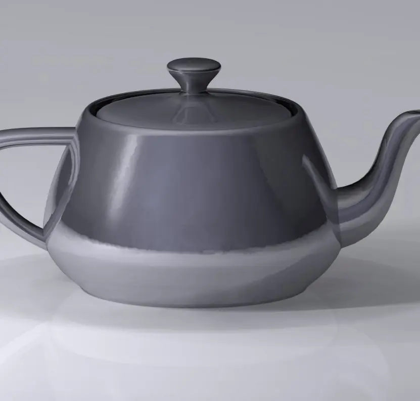


5.5.1 Eight applications of 3D transformations, projection and viewing
- 3D games and mobile games. Every frame of a game applies model, view and projection matrices to the vertices of each object. The same few 4 × 4 matrices move the characters, turn the camera and give the scene its depth. Games played on a phone in Nepal run this pipeline on the phone's own GPU, dozens of times per second.
- Architecture and engineering drawings (CAD). Engineers designing a bridge, a road cutting or a hydropower tunnel rotate and scale the 3D model to inspect it from every side. Orthographic projection gives the plan, front and side views that builders can measure with a scale rule. Perspective views are used to show a client how the finished building will look.
- Maps and terrain viewers. A 3D map of the Himalayas tilts the camera and projects the terrain with perspective, so distant peaks look smaller and ridges converge. The viewing transformation moves the virtual camera as the user drags the screen. Trekking and tourism applications use it to let a visitor preview a route before walking it.
- Virtual reality and heritage tours. A VR headset renders the scene twice, once for each eye, from two camera positions a few centimetres apart. Each picture is a perspective projection, and the small difference gives the feeling of depth. Virtual walkthroughs of temple squares in the Kathmandu valley can be built in this way for students who cannot travel.
- Medical imaging. CT and MRI scanners produce stacks of slices that software turns and projects so that a doctor can look at an organ from any angle. Rotations keep lengths and angles unchanged, so measurements taken on the screen remain valid. Hospitals that own a CT scanner rely on these transformations when they show a 3D view of a bone fracture.
- Film, animation and advertising. Animators place objects and a virtual camera using translations and rotations, and keep the rotations as quaternions to avoid gimbal lock. The camera path and the lens (field of view) are then projected into the final frames. Animation and advertising studios in Kathmandu use these tools to produce television commercials.
- Robotics and drones. A robot arm is a chain of joints, and the position of its hand is found by multiplying one rotation and translation matrix per joint. A survey drone relates its camera, its own body and the ground by a similar chain of 4 × 4 matrices. The same maths turns photographs into 3D terrain models for land measurement.
- Education and product visualisation. A molecule viewer lets a chemistry student rotate a model, and an online shop lets a customer spin a 3D model of a phone or a pair of shoes. Both simply apply a rotation matrix to the vertices and re-project them after every mouse movement. This makes difficult 3D shapes understandable on a flat screen.


Chapter summary
- 3D transformations are 4 × 4 matrices; rotations about x, y, z are orthogonal matrices with determinant 1; order of composition matters.
- Orthographic projection drops z; perspective projection divides by depth: x′ = x·d/z, y′ = y·d/z, via a matrix and a perspective divide.
- Perspective causes foreshortening and vanishing points; parallel projection preserves parallel lines and sizes.
- Viewing needs an eye, a look-at point and an up vector, a view volume (frustum) and a pipeline ending in the viewport transform.
- Back-face culling tests N · V > 0 using the polygon normal.
Practice
- Write the 4 × 4 matrix for translation by (3, −2, 5).
- Rotate (0, 1, 0) by 90° about the x-axis.
- Rotate (1, 0, 0) by 90° about the z-axis then 90° about the y-axis. Give the final point.
- Project the point (4, 2, 8) with perspective projection d = 4.
- Why does perspective projection need a division by depth?
- What is a vanishing point?
- Differentiate orthographic and oblique projection.
- Compute the normal of the triangle (0, 0, 0), (1, 0, 0), (0, 1, 0) taken in that order.
- For viewer direction V = (0, 0, 1), is the triangle in question 8 front-facing?
- Why is back-face culling not enough for hidden-surface removal?
Answers and worked solutions
1. Identity with last column (3, −2, 5, 1).
2. Rotation about x maps (y, z) → (y cos θ − z sin θ, y sin θ + z cos θ) = (0 − 0, 1 + 0) → y′ = 0, z′ = 1: (0, 0, 1).
3. About z: (1, 0, 0) → (0, 1, 0). About y: the matrix [[0, 0, 1], [0, 1, 0], [−1, 0, 0]] applied to (0, 1, 0) gives (0, 1, 0). Final point (0, 1, 0) (it lies on the y-axis, which the y-rotation leaves fixed).
4. x′ = 4·4/8 = 2, y′ = 2·4/8 = 1: (2, 1).
5. Similar triangles: image size is proportional to 1/distance, which is a division by z.
6. The point at which projections of parallel lines (not parallel to the image plane) meet.
7. Orthographic projectors are perpendicular to the projection plane; oblique projectors are parallel to each other but slanted.
8. (1, 0, 0) × (0, 1, 0) = (0, 0, 1).
9. N · V = 1 > 0: front-facing.
10. It only removes faces pointing away; two front-facing surfaces can still overlap, so their depth order must be resolved (Z-buffer, painter's algorithm).
Model answers: medium (5 marks) and long (10 marks) questions
Q1 (5 marks). A vertical line passes through (x, z) = (1, 1). Find the new position of P(4, 1, 3) after a rotation of 90° about this line, writing the composite matrix.
Introduction. The line is parallel to the y-axis, so we move it to the y-axis, rotate about y, and move it back (section 5.1, Figure 5.1).
- Translate the axis to the origin. T(-1, 0, -1) subtracts (1, 0, 1), so P becomes (3, 1, 2).
- Rotate about y by 90°. The y-rotation sends (x, z) to (z, -x), so (3, 1, 2) becomes (2, 1, -3). The height y does not change.
- Translate back. T(1, 0, 1) adds (1, 0, 1), giving (3, 1, -2).
- Composite matrix. M = T(1, 0, 1) · Ry(90°) · T(-1, 0, -1), applied right to left:
[  0   0   1   0 ]
[  0   1   0   0 ]
[ -1   0   0   2 ]
[  0   0   0   1 ]
Check. M (4, 1, 3, 1) = (0·4 + 1·3, 1, -4 + 2, 1) = (3, 1, -2, 1). Before and after, the point is √(3² + 2²) = 3.61 units from the axis, as a rotation must keep it.
If the order were reversed, the rotation would be about the wrong line, which shows that the order of matrices matters.
Conclusion. Rotation about any line parallel to an axis is translate, rotate, translate back; the answer is P′ = (3, 1, -2).
Q2 (5 marks). Project the triangle (2, 2, 4), (4, 2, 4), (3, 4, 6) with a perspective projection from the origin onto the plane z = 2, and compare it with the orthographic projection.
Introduction. In perspective projection the projectors pass through the eye, so each point maps to x′ = x·d/z and y′ = y·d/z with d = 2 (section 5.2, Figures 5.2 and 5.3).
Homogeneous form. Multiplying (x, y, z, 1) by the matrix with 1/d in the last row gives (x, y, z, z/d); the perspective divide then divides every coordinate by w = z/d.
| Vertex | (x, y, z) | Homogeneous (x, y, z, w) | Perspective (x′, y′) | Orthographic (x, y) |
|---|---|---|---|---|
| P1 | (2, 2, 4) | (2, 2, 4, 2) | (1.000, 1.000) | (2, 2) |
| P2 | (4, 2, 4) | (4, 2, 4, 2) | (2.000, 1.000) | (4, 2) |
| P3 | (3, 4, 6) | (3, 4, 6, 3) | (1.000, 1.333) | (3, 4) |
Comparison. P1 and P2 are at depth 4 and are scaled by d/z = 0.50; P3 is farther, at depth 6, and is scaled by 0.333.
The orthographic triangle has base 2 and height 2, so its area is 2; the perspective triangle has base 1 and height 0.333, so its area is 0.167, only 1/12 as large.
The perspective picture also loses equal scale, because the farther vertex shrinks more.
Conclusion. Perspective gives realistic foreshortening and keeps depth in w; orthographic projection keeps true sizes and is preferred for drawings.
Q3 (5 marks). Explain back-face detection. A viewer is at E = (0, 0, 10). Decide whether the triangles A(2, 0, 5), B(4, 0, 5), C(2, 3, 5) and A(1, 1, 1), B(1, 3, 1), C(3, 1, 1), each listed anticlockwise, are visible.
Introduction. In a closed solid, faces that point away from the viewer cannot be seen, so they can be discarded before drawing (section 5.4, Figure 5.6). This back-face culling removes about half of the polygons of a typical model.
Method. Compute the normal N = (B - A) × (C - A) with the vertices in anticlockwise order, let V be the vector from the face to the viewer, and test N · V. If it is greater than 0 the face is front-facing; otherwise it is a back face.
| Triangle | N = (B - A) × (C - A) | V = E - centroid | N · V | Decision |
|---|---|---|---|---|
| 1: (2,0,5), (4,0,5), (2,3,5) | (2,0,0) × (0,3,0) = (0, 0, 6) | (-2.667, -1, 5) | 30 | visible |
| 2: (1,1,1), (1,3,1), (3,1,1) | (0,2,0) × (2,0,0) = (0, 0, -4) | (-1.667, -1.667, 9) | -36 | culled |
Triangle 1 faces +z, towards the viewer, so it is drawn. Triangle 2, although listed anticlockwise when seen from its own side, faces -z and so points away from the viewer.
Limitation. Back-face culling does not decide the order of two front-facing faces that overlap; hidden-surface methods such as the Z-buffer (Unit 6) are still needed.
Q4 (10 marks). Compare parallel and perspective projection, and describe the 3D viewing pipeline, with a worked example.
Introduction. A screen is flat, so a 3D scene must be projected onto a 2D plane. The choice of projection and the sequence of coordinate changes before it are the heart of 3D graphics (sections 5.2 and 5.3, Figures 5.3 to 5.5).
- Projectors. In parallel projection the projectors are parallel; in perspective projection they meet at the centre of projection, the eye.
- Orthographic projection. The projectors are perpendicular to the plane, and the matrix simply drops z, so (x, y, z) becomes (x, y). Lengths parallel to the plane are exact, which suits plans and elevations.
- Oblique and axonometric projection. Cavalier and cabinet projections slant the projectors so that one face keeps its true shape; isometric projection shows three faces with equal foreshortening.
- Perspective projection. By similar triangles x′ = x·d/z and y′ = y·d/z. The cube of side 2 at depths 4 and 6 shrinks to ±0.50 and ±0.333, so the far face is smaller by 6/4 = 1.50.
- Vanishing points. Lines parallel to the view direction converge to a vanishing point, giving one-, two- or three-point perspective.
- View volume. A box for orthographic projection and a frustum, bounded by the near and far planes and four side planes, for perspective projection; everything outside is clipped.
- Viewing pipeline. World → (view matrix) camera → (projection matrix) clip → clipping → (divide by w) normalised device → (viewport) screen.
- Worked example. A camera at (0, 0, 10) looking at the origin sees the world point (1, 2, 3) at (1, 2, -7). With a 90° field of view, aspect 1, near 1 and far 10 the clip coordinates are (1, 2, 6.333, 7); dividing by w = 7 gives (0.143, 0.286, 0.905), and an 800 × 800 viewport puts it at pixel (457, 286).
| Parallel (orthographic) | Perspective | |
|---|---|---|
| Projectors | Parallel | Meet at the eye |
| Size and distance | Unchanged | Shrinks with distance |
| Parallel lines | Stay parallel | Converge at vanishing points |
| Matrix | Drops z (affine) | Uses w = z/d (not affine) |
| View volume | Box | Frustum |
| Typical use | CAD, drawings | Games, film, VR |
Conclusion. Orthographic projection preserves measurements and perspective projection preserves realism. Both are carried out by the same pipeline of matrices, so a renderer can switch between them by changing only the projection matrix.