Unit 5 · 10 teaching hours · 38 min read
Data Communication and Computer Network
What the syllabus asks for 8
- Data communication fundamentals
- Transmission media
- Network types and topologies
- Network devices
- Layered models: OSI and TCP/IP
- Addressing: MAC and IP
- Wireless and mobile networks
- Advantages, limitations and uses of computer networks
A computer on its own is useful; computers joined together are transformative. Data communication is the exchange of data between devices over a medium; a computer network is a set of such devices that can share data and resources.
This unit covers the signals, media, topologies, devices, layered models and addressing that every networking course builds on.
- Components, signals, bandwidth, transmission modes; Shannon's formula.
- Guided and unguided media; multiplexing; switching.
- Network types and topologies; network devices.
- OSI and TCP/IP models; IP addressing and subnetting with worked examples.
5.1 Data communication fundamentals
Components of a communication system: sender (source), receiver (destination), message, transmission medium and protocol (the agreed rules).
Signals. An analog signal varies continuously (sound); a digital signal has discrete levels (0 and 1). A modem (modulator–demodulator) converts digital data to analog form for a telephone line or radio link and back.
Bandwidth has two senses: in hertz, the range of frequencies a channel carries; in bits per second (bps), its capacity. Throughput is the data rate actually achieved; latency is the delay; jitter is variation in delay.
Noise, attenuation (loss of strength with distance) and distortion degrade signals.
Shannon's capacity for a noisy channel: C = B × log₂(1 + S/N), where B is bandwidth in Hz and S/N the signal-to-noise ratio (a plain ratio, not dB).
A telephone line has B = 3000 Hz and S/N = 1000 (30 dB). C = 3000 × log₂(1001) = 3000 × 9.967 ≈ 29,900 bps, about 29.9 kbps; no coding can beat this.
Time to send a 1 MB file (8 × 10⁶ bits) on an 8 Mbps link: 8 × 10⁶ / 8 × 10⁶ = 1 s (ignoring protocol overhead and propagation delay).
Transmission modes
| Mode | Direction | Example |
|---|---|---|
| Simplex | one way only | keyboard → computer, radio broadcast |
| Half duplex | both ways, one at a time | walkie-talkie |
| Full duplex | both ways simultaneously | telephone, modern Ethernet |
Serial vs parallel: serial sends bits one after another on one line (USB, Ethernet; cheap over distance); parallel sends several bits at once on many lines (old printer port; skew limits distance).
Asynchronous transmission frames each byte with start and stop bits; synchronous sends blocks timed by a shared clock.
Error detection adds redundancy: a parity bit, a checksum, or a CRC (cyclic redundancy check), used in Ethernet. Detected errors are corrected by retransmission (ARQ) or by error-correcting codes.
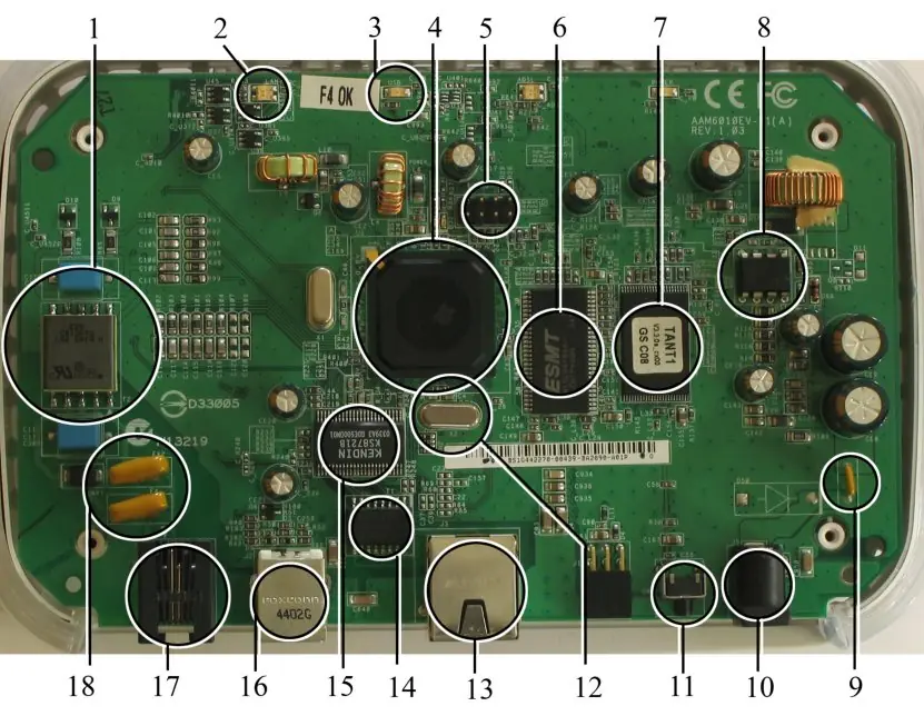


5.2 Transmission media
| Medium | Type | Speed / range (typical) | Notes |
|---|---|---|---|
| Twisted pair (UTP/STP) | guided, copper | Cat5e/Cat6: 1 Gbps to 100 m | cheap; LAN cabling, RJ-45 plug |
| Coaxial cable | guided, copper | up to ~10 Mbps (old Ethernet), more on cable TV | better shielding than twisted pair |
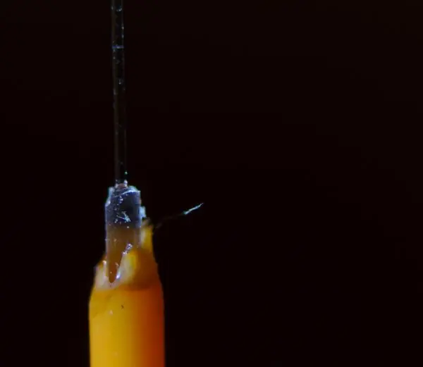
| Optical fibre | guided, glass | Gbps to Tbps over kilometres | immune to electrical noise; single-mode for long haul, multi-mode for short |
| Radio / Wi-Fi | unguided | 2.4, 5, 6 GHz bands | shared, interference, security needs |
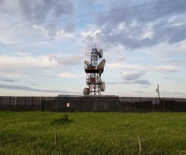
| Microwave | unguided | line of sight, ~50 km between towers | tower links across hills |
| Satellite | unguided | worldwide; high latency (GEO ~250 ms one way) | remote villages, VSAT |
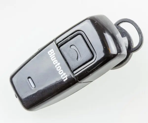
| Infrared, Bluetooth | unguided | short range | remotes, peripherals |
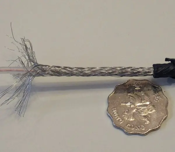
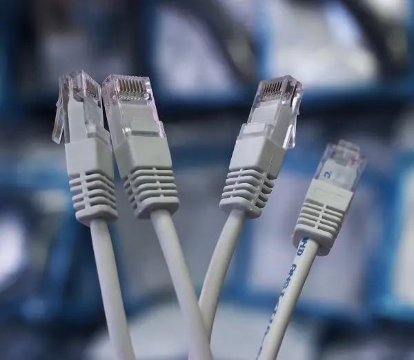
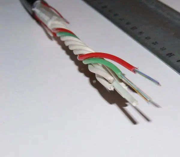
Multiplexing shares one link among many signals: FDM (different frequencies), TDM (different time slots), WDM (different light colours on fibre).
Switching moves data through a network: circuit switching reserves a dedicated path for the whole call (telephone); packet switching cuts data into packets that are routed independently and reassembled (the Internet).
5.2.1 Eight points to weigh when choosing a medium
- Speed (bandwidth). The medium must carry the data rate you need today and in five years. Cat-6 twisted pair is enough for a 1 Gbps college lab, but a bank's backbone between floors needs fibre. Always check the cable category printed on the jacket.
- Distance. Twisted pair works only to 100 m between switch and computer, because the signal fades. Fibre can run tens of kilometres before it needs a repeater. Between two hill-top towers in Nepal, microwave can cover about 50 km in line of sight.
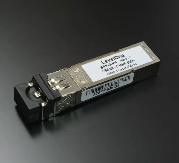
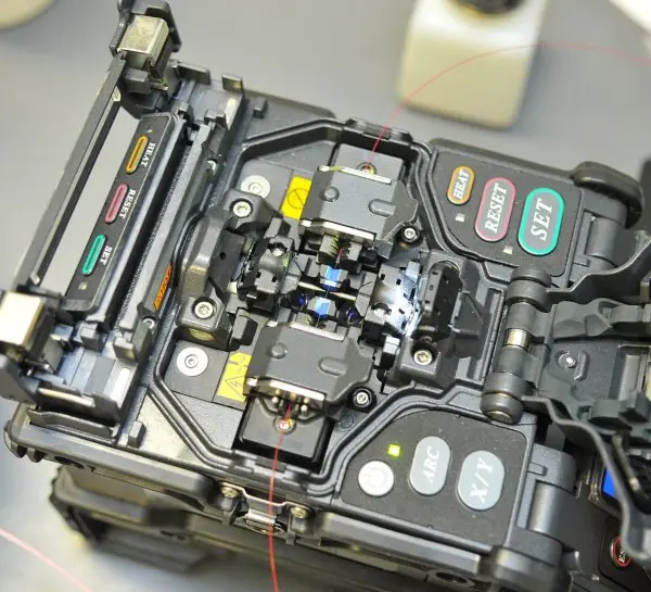
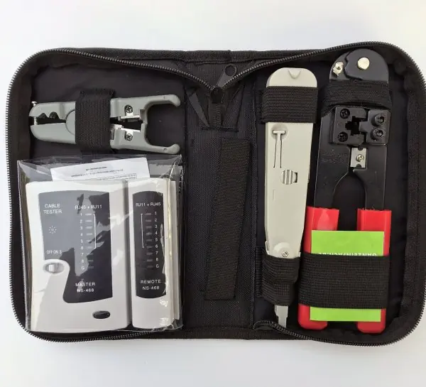
- Cost. UTP cable and RJ-45 plugs are the cheapest option and any technician can fit them with a crimp tool. Fibre cable itself is not costly now, but splicing and optical modules are. Satellite links cost the most per megabit.
- Noise and interference. Copper picks up electrical noise from motors, lifts and power lines. Fibre carries light, so it is not affected by such noise and is the safe choice in a factory. Shielded cable (STP) is the middle way.
- Security. Light inside a fibre or current inside a cable is hard to tap without cutting it. Radio waves can be received by anyone in range, so Wi-Fi must be encrypted with WPA2 or WPA3. Banks keep core links on cable for this reason.
- Installation and terrain. Cables need trenches or conduits, which is hard on a steep Himalayan slope. Radio, microwave and satellite reach such places without digging. Cutting of cables by road-widening work is a common cause of outages in Nepal.
- Mobility. Only wireless media let a phone or laptop move around. A classroom with Wi-Fi allows students to connect anywhere, while a wired lab does not. Use cable for fixed servers and wireless for people.
- Reliability and maintenance. Fibre and good copper last for decades with little care. Wireless links suffer from rain, fog and crowding on the same frequency. Network engineers therefore keep a backup path for important links.
5.3 Network types and topologies
By scale
| Type | Area | Example |
|---|---|---|
| PAN | a person (a few metres) | Bluetooth earphones |
| LAN | a room, building or campus | college computer lab |
| MAN | a city | cable TV or ISP metro network |
| WAN | country or world | the Internet, bank branch network |
Other kinds: client–server (dedicated servers serve clients) and peer-to-peer (each machine is both); intranet (private network using internet technology), extranet (intranet shared with partners), VPN (private tunnel over the public Internet).
Topology is the layout of the network.
| Topology | Layout | Advantage | Disadvantage |
|---|---|---|---|
| Bus | all nodes on one backbone cable | little cable, cheap | backbone break kills the network; collisions |
| Ring | each node connected to two neighbours in a loop | orderly access | one break stops a simple ring |
| Star | every node connected to a central hub/switch | easy to add and troubleshoot; a bad cable affects one node | central device is a single point of failure |
| Mesh | nodes interconnected; full mesh has n(n−1)/2 links | very reliable | costly cabling |
| Tree | star networks joined in a hierarchy | scalable | root failure splits tree |
| Hybrid | a mix | flexible | complex |
A full mesh of 6 nodes needs 6 × 5 / 2 = 15 links, and each node needs 5 ports.


5.4 Network devices
| Device | Layer | Function |
|---|---|---|
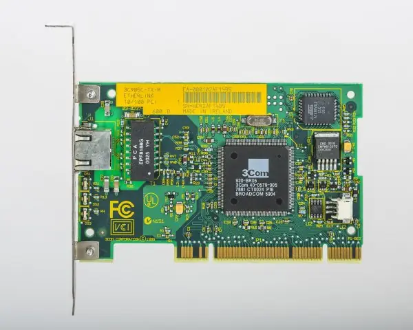
| NIC | 1–2 | the card/chip connecting a host to the network; has a MAC address |
| Repeater | 1 | regenerates a weak signal |
| Hub | 1 | repeats incoming bits to all ports |
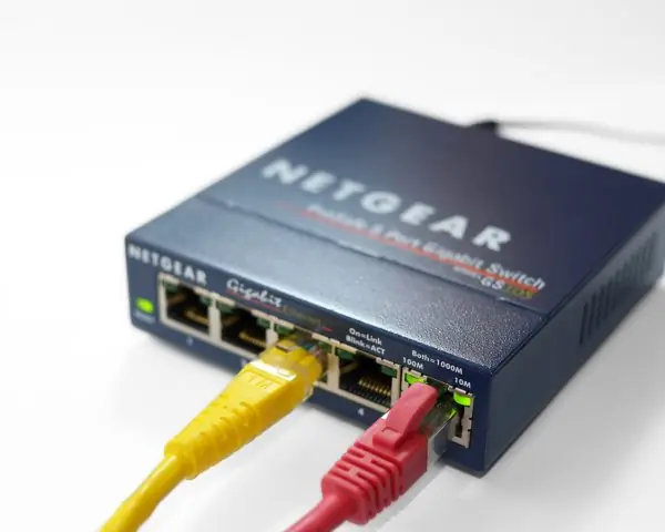
| Switch | 2 | forwards frames only to the port of the destination MAC (learns addresses) |
| Bridge | 2 | joins two LAN segments |
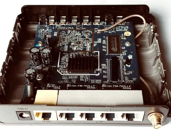
| Router | 3 | forwards packets between networks using IP addresses; chooses routes |
| Gateway | 4–7 | translates between different protocol families |
| Modem | 1 | digital ↔ analog conversion |
| Access point | 1–2 | connects wireless clients to a wired network |
| Firewall | 3–7 | filters traffic by rules |
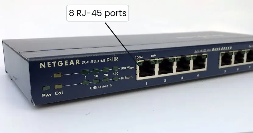

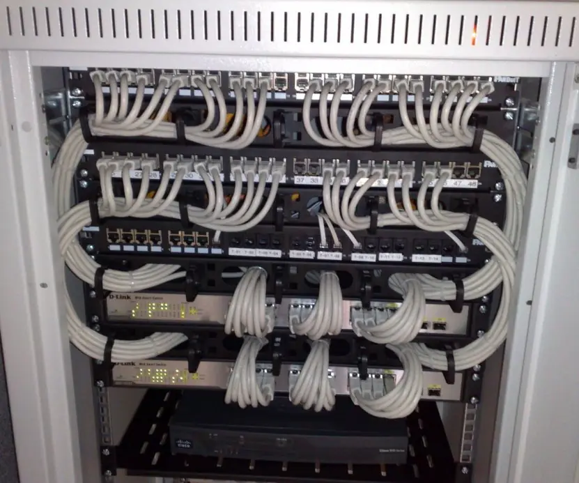

5.5 Layered models: OSI and TCP/IP
Layering splits a complicated job into stages; each layer uses the services of the layer below and hides its details from the layer above.
| # | OSI layer | Job | Data unit | Examples |
|---|---|---|---|---|
| 7 | Application | services to user programs | data | HTTP, SMTP, FTP, DNS |
| 6 | Presentation | format, encryption, compression | data | TLS, JPEG, ASCII/Unicode |
| 5 | Session | open, manage, close dialogues | data | sockets, RPC |
| 4 | Transport | end-to-end delivery, ports, reliability | segment | TCP, UDP |
| 3 | Network | logical addressing, routing | packet | IP, ICMP |
| 2 | Data link | node-to-node delivery, MAC addressing, error detection | frame | Ethernet, Wi-Fi, PPP |
| 1 | Physical | bits on the medium | bits | cables, signals |
Memory aid, top to bottom: All People Seem To Need Data Processing.
The TCP/IP model has four layers: Application (OSI 5–7), Transport (TCP/UDP), Internet (IP), Network access (OSI 1–2). It is the model the Internet actually uses; OSI is the teaching reference.
- TCP: connection-oriented, reliable, ordered (three-way handshake: SYN, SYN-ACK, ACK). Used for web, email, file transfer.
- UDP: connectionless, no guarantee, low delay. Used for DNS queries, video calls, games.
Common application protocols: HTTP 80 / HTTPS 443, FTP 21, SSH 22, SMTP 25, DNS 53, POP3 110, IMAP 143.

5.6 Addressing: MAC and IP
- MAC address: 48-bit hardware address burned into the NIC, written like
3C:52:82:1A:9F:07; works inside one LAN. - IPv4 address: 32 bits written as four decimal bytes (dotted decimal), e.g.
192.168.10.25; gives about 4.3 billion addresses. IPv6 has 128 bits (2001:db8::1) because IPv4 ran out.
Classful ranges (historical): A 1–126 (mask /8), B 128–191 (/16), C 192–223 (/24), D 224–239 multicast, E 240–255 reserved. Modern networks use CIDR, writing the prefix length: 192.168.10.0/26.
Private ranges (not routed on the Internet): 10.0.0.0/8, 172.16.0.0/12, 192.168.0.0/16. 127.0.0.1 is loopback (this machine).
A subnet mask marks which bits are the network part (1s) and which are the host part (0s). In a network with h host bits, there are 2ʰ addresses, of which the first (network address) and last (broadcast) are not usable, so usable hosts = 2ʰ − 2.
Four subnets need 2 extra bits, so the prefix becomes /26 and the mask is 255.255.255.192 (the last byte 11000000 = 192). Host bits h = 6, so each subnet has 2⁶ = 64 addresses and 62 usable hosts.
| Subnet | Network address | Usable range | Broadcast |
|---|---|---|---|
| 1 | 192.168.10.0 | .1 – .62 | 192.168.10.63 |
| 2 | 192.168.10.64 | .65 – .126 | 192.168.10.127 |
| 3 | 192.168.10.128 | .129 – .190 | 192.168.10.191 |
| 4 | 192.168.10.192 | .193 – .254 | 192.168.10.255 |
Host 172.16.37.200 with mask 255.255.255.0 (/24). AND the address with the mask byte by byte: 172.16.37.(200 AND 0) = 172.16.37.0. A host 172.16.38.5 with the same mask is on 172.16.38.0, a different network, so they need a router to talk.


Other services: DHCP hands out IP addresses automatically; DNS maps names such as tu.edu.np to IP addresses; NAT lets a whole home network share one public IP; ARP finds the MAC address that goes with an IP on the LAN; ICMP carries errors and powers ping.
5.7 Wireless and mobile networks
Wi-Fi (IEEE 802.11) gives LAN access by radio; Bluetooth gives short-range PAN links; cellular networks (2G, 3G, 4G LTE, 5G) cover wide areas through cells served by base stations; NFC works within a few centimetres (contactless payment).
In Nepal, Wi-Fi in homes and colleges, FTTH broadband and 4G (and now 5G trials) are the everyday forms.

5.7.1 Eight uses of wireless and mobile networks in Nepal
- Mobile banking and wallets. eSewa, Khalti, IME Pay and bank apps run over 4G and Wi-Fi. A shopkeeper in Pokhara can accept a Fonepay QR payment in a few seconds. Without mobile data, this would need a visit to the bank.
- Government services. The Nagarik App and online forms of departments are used from phones. Citizens can check a licence or a tax record without travelling to Kathmandu. This saves time, travel cost and queues.
- Online classes and exams. During the COVID lockdown, schools and campuses moved to Zoom and Google Meet over mobile data and home Wi-Fi. Tribhuvan University result and registration portals are still checked on phones today. Wireless access has become part of ordinary study.
- Remote and hill areas. Microwave and VSAT links connect health posts and schools where no cable is possible. A telemedicine consultation can reach a village in Humla from a doctor in a city hospital. Such links need only a dish, a solar panel and a router.
- Emergency alerts. SMS and cell broadcast warn people of floods, landslides and earthquakes. After the 2015 earthquake, phones were the main way for families to find each other. Battery-backed towers keep service going when the grid fails.
- Transport and ride sharing. Pathao and InDrive use GPS and mobile data to match riders with drivers. Ticketing apps for buses and flights work the same way. Drivers also share live location with relatives.
- Agriculture and weather. Farmers receive market prices and weather forecasts by SMS or app. Some dairy cooperatives record milk at collection centres on tablets that sync over mobile data. Better information helps farmers decide when to sell.
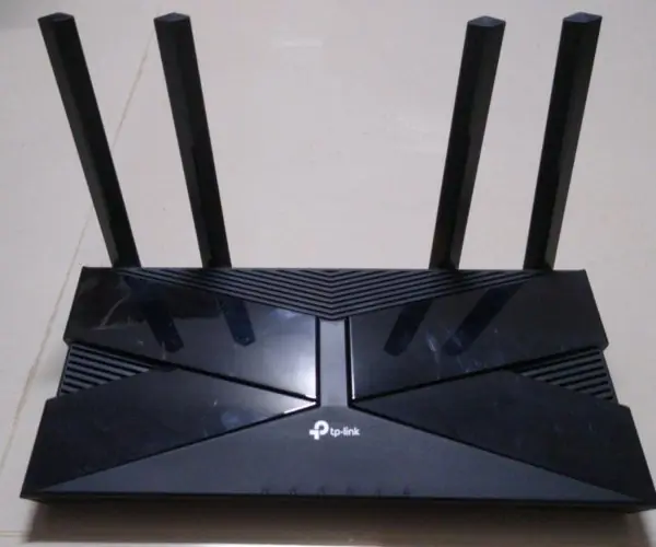
- Home and campus Wi-Fi. FTTH broadband from ISPs ends in a Wi-Fi router that serves phones, laptops and smart TVs. College labs add access points so students can bring their own devices. Good placement of access points matters more than the number of antennas.
5.8 Advantages, limitations and uses of computer networks
5.8.1 Eight advantages of computer networks
- Resource sharing. One printer, one scanner or one large disk can serve every computer in a lab. A college buys one good laser printer for the office instead of ten cheap ones. Software licences and internet connections are shared in the same way.
- Fast communication. E-mail, chat and video calls deliver a message in seconds, not days. A teacher in Biratnagar can send a notice to 500 students at once. Offices stop depending on peons and paper circulars.
- Central data and easy backup. When files are kept on a server, everyone sees the same latest copy. The administrator can back up one machine every night instead of asking each user. This is how Tribhuvan University exam sections keep result files safe.
- Lower cost. Sharing hardware, software and links cuts the total cost of an organisation. A bank branch uses the head-office database through the network instead of keeping its own. Licences for network versions are usually cheaper than one copy per computer.
- Better reliability. Important data can be copied to two or more machines, so a single failure does not stop work. If one server fails, a second takes over. Banks and hospitals use this to run 24 hours a day.
- Scalability. New computers can be plugged in as an office grows, by adding a switch port or a Wi-Fi access point. The network does not have to be rebuilt. A school can start with ten computers and grow to a hundred.
- Centralised security and control. The administrator can set user names, passwords and permissions in one place. A student can read the shared notes folder but cannot delete it. Firewalls and antivirus on the server protect every connected computer.
- Remote access and cooperation. People can work together on the same document from different cities, and staff can reach office files from home through a VPN. Services such as ConnectIPS and Nagarik App exist only because networks join citizens to government and bank computers. This saves travel time and cost.
5.8.2 Eight limitations of computer networks
- High set-up cost. Cables, switches, routers, servers and skilled engineers cost a lot at the start. A new college lab may spend more on the network than on the computers. Costs fall only when many users share the system.
- Security risks. Many connected machines give an attacker many doors. A virus or ransomware that enters one computer can spread through the whole network. Strong passwords, updates and firewalls are needed all the time.
- Dependence on the server and links. If the main server, switch or internet link fails, many users stop working together. Offices in Nepal feel this when the ISP link or the power fails. A backup link and UPS reduce the damage.
- Need for skilled staff. A network needs an administrator to add users, fix faults and apply patches. Small organisations often cannot afford a full-time person. Poor management leads to slow and insecure systems.
- Congestion and slow speed. When too many users share one link, everyone is slow. A lab where forty students download videos at once can choke a 20 Mbps connection. Better planning and traffic control are the cures.
- Privacy and misuse. Data stored centrally can be copied or read by the wrong person. Staff may waste time on social media or share pirated files. Policies and monitoring are needed, and users must be told about them.
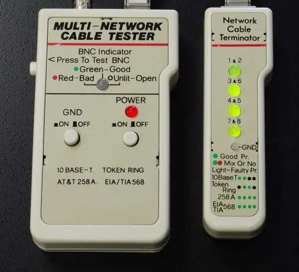
- Cable and equipment faults. A broken cable, a bad connector or a loose port can cut off a computer or a whole segment. Finding the fault in a building with hundreds of cables is slow. Labelled cables and testers (Plate 5.3) help.
- Compatibility and maintenance. Devices from different makers or of different ages may not work well together. Software must be updated on every machine, and old equipment must be replaced in time. This work never ends.
5.8.3 Eight applications of computer networks in Nepal
- Banking and payments. ATM, mobile banking, ConnectIPS, eSewa, Khalti and Fonepay QR all run on networks that link branches, shops and phones to bank servers. A transfer made in Dhankuta is visible in Kathmandu in a second. Secure links and encryption protect the money.
- Government services. The Nagarik App, the online passport and driving-licence systems, the Inland Revenue portal and the Department of Customs use networks to serve citizens. Offices in different districts read the same database. This reduces the number of visits to government offices.
- Education. Tribhuvan University results, registration and the NEB exam system work through websites. Colleges use Wi-Fi, e-libraries and learning platforms such as Google Classroom. Students in remote districts can attend classes online.
- Health. Hospitals link reception, laboratory, pharmacy and billing on one LAN. Telemedicine programmes connect health posts to specialist doctors through broadband or VSAT. Reports reach the doctor before the patient does.
- Communication. Mobile calls, SMS, Viber, WhatsApp and e-mail all use the Nepal Telecom, Ncell and ISP networks. Families with members in Qatar or Malaysia keep in touch daily by video call. Remittance information travels on the same networks.
- Business and e-commerce. Online shops such as Daraz take orders, payments and delivery tracking over networks. Small traders sell through Facebook pages and receive money by QR. Supply chains use networked billing and stock software.
- Transport and tourism. Airline and bus booking systems, hotel reservations and ride apps need always-on networks. Trekking agencies use GPS and satellite phones in the mountains. Tourists book flights to Lukla from abroad.
- Media and entertainment. Video streaming, online news and FM radio over the internet reach audiences in every district. Television channels send programmes to cable operators over fibre and satellite links. Gaming and social networks add to the traffic.
Formula and fact sheet
- Shannon: C = B log₂(1 + S/N). Transfer time = bits / rate.
- Full-mesh links = n(n − 1)/2.
- Usable hosts = 2ʰ − 2; subnet size 2ʰ; mask from prefix /n.
- OSI: Physical, Data link, Network, Transport, Session, Presentation, Application.
- TCP reliable; UDP fast. Ports: HTTP 80, HTTPS 443, SMTP 25, DNS 53, FTP 21.
- Hub = layer 1 (broadcasts), switch = layer 2 (MAC), router = layer 3 (IP).
- Private IPv4: 10/8, 172.16/12, 192.168/16.
Chapter summary
- Communication needs a sender, receiver, message, medium and protocol; capacity is limited by bandwidth and noise.
- Media may be guided (twisted pair, coax, fibre) or unguided (radio, microwave, satellite).
- Networks are classified by scale (PAN, LAN, MAN, WAN) and by topology (bus, ring, star, mesh, tree).
- Switches work on MAC addresses; routers on IP addresses; layered models (OSI, TCP/IP) divide the work.
- IPv4 addresses split into network and host parts by a mask; subnetting divides a network into smaller ones.
Practice
A. Short questions
- List the five components of a data communication system.
- Differentiate simplex, half duplex and full duplex with examples.
- Differentiate hub, switch and router.
- Why is fibre preferred over copper for backbones?
- Differentiate LAN, MAN and WAN.
- Differentiate TCP and UDP.
- What is the role of DNS and DHCP?
- Compare star and bus topologies.
B. Numerical problems
- A channel has B = 4 kHz and S/N = 255. Find the Shannon capacity.
- How many links does a full mesh of 10 computers need?
- For 10.0.0.0/8 write the mask and the number of usable hosts.
- Divide 192.168.5.0/24 into 8 equal subnets: give the mask, the size and the network addresses.
- A 25 MB file is sent over a 20 Mbps link. Find the ideal time.
C. Long questions
- Explain the seven layers of the OSI model with the function of each.
- Describe the network topologies with their merits and demerits.
- Compare circuit switching and packet switching.
- Differentiate hub, switch and router (5 marks).
- Describe the transmission media with merits and demerits.
- Divide 192.168.10.0/24 among departments of 100, 50, 25 and 10 hosts (5 marks).
- What is a computer network? Give its advantages, disadvantages and applications.
- How are errors detected? Explain parity, checksum and CRC (5 marks).
Answers and worked solutions
1. Sender, receiver, message, medium, protocol.
2. Simplex: one direction only (keyboard). Half duplex: both ways but alternately (walkie-talkie). Full duplex: both ways at once (telephone).
3. Hub repeats bits to all ports; switch forwards frames to the port of the destination MAC; router forwards packets between networks by IP.
4. Fibre has far higher bandwidth, low loss over long distance, and no electromagnetic interference.
5. LAN: building or campus; MAN: a city; WAN: countries or the world.
6. TCP: connection-oriented, reliable, ordered, with flow control. UDP: connectionless, unreliable but fast and light.
7. DNS translates domain names into IP addresses; DHCP automatically assigns IP configuration to hosts.
8. Star: central switch, a cable fault isolates one node, easy to extend, but the switch is a single point of failure. Bus: single cable, cheap, but a backbone fault stops everything and performance falls with load.
9. C = 4000 × log₂(256) = 4000 × 8 = 32,000 bps.
10. 10 × 9 / 2 = 45 links.
11. Mask 255.0.0.0; host bits 24, usable = 2²⁴ − 2 = 16,777,214.
12. 8 subnets need 3 bits → /27, mask 255.255.255.224, size 32. Networks: 192.168.5.0, .32, .64, .96, .128, .160, .192, .224 (30 usable hosts each).
13. 25 MB = 25 × 8 = 200 Mbit; 200 / 20 = 10 s.
14. Use the table in §5.5, adding one sentence on the protocol/example for each layer. 14–16. Full ten-mark and five-mark answers, with Figures 5.2 and 5.4, are in the section Model answers that follows.
16. Circuit switching: a path reserved end to end, constant delay, wasted when idle, used by classic telephony. Packet switching: data cut into packets routed independently, efficient sharing, variable delay, the basis of the Internet. 17–21. Full model answers (Q17-M to Q21-M) are in the section that follows; each uses Plates 5.1 to 5.7 and Figures 5.1 to 5.6.
Model answers: medium (5 marks) and long (10 marks) questions
Q14. Explain the seven layers of the OSI model with the function of each. (10 marks)
Introduction. The OSI (Open Systems Interconnection) model, published by ISO in 1984, divides network communication into seven layers.
Each layer serves the layer above it and is served by the layer below, so hardware and software from different makers can work together (Figure 5.4).
The seven layers (from top to bottom)
- Application (7): gives network services to user programs, such as web browsing, email and file transfer. Protocols: HTTP, SMTP, FTP, DNS.
- Presentation (6): translates, compresses and encrypts data so both ends understand it (ASCII/Unicode, JPEG, TLS).
- Session (5): opens, manages and closes a dialogue between two applications and adds checkpoints for recovery.
- Transport (4): end-to-end delivery between processes using port numbers; splits data into segments and provides flow control and error recovery. Protocols: TCP (reliable), UDP (fast).
- Network (3): logical addressing and routing of packets across networks. Protocols: IP, ICMP; device: router.
- Data link (2): moves frames between two directly connected nodes using MAC addresses, with error detection (CRC) and access control. Devices: switch, bridge.
- Physical (1): sends raw bits as electrical, light or radio signals; defines cables, connectors, voltages and data rates. Devices: hub, repeater, NIC.
Data units. Data become segments at transport, packets at network, frames at data link and bits at the physical layer. Each layer adds a header while the data go down (encapsulation) and removes it on the way up at the receiver.
| Layer | PDU | Address used | Device |
|---|---|---|---|
| Transport | segment | port | firewall (L4) |
| Network | packet | IP address | router |
| Data link | frame | MAC address | switch |
| Physical | bits | none | hub, cable |
Conclusion. The OSI model is a reference model that makes network design and troubleshooting easier because a fault can be traced layer by layer. The Internet itself runs on the simpler TCP/IP model.
A useful memory aid, from the top, is "All People Seem To Need Data Processing".
Q15. Describe the network topologies with their merits and demerits. (10 marks)
Introduction. A topology is the arrangement of the nodes and links of a network. The physical topology is the real cabling, and the logical topology is the path the data follow. The five common topologies are shown in Figure 5.2.
Topologies
- Bus: all nodes attach to one backbone cable with a terminator at each end. Merits: cheap, easy to extend, little cable. Demerits: one break in the backbone stops everyone, performance falls as nodes are added, and collisions occur.
- Star: every node connects to a central hub or switch. Merits: easy to install and troubleshoot, one cable failure affects only one node. Demerits: the central device is a single point of failure and more cable is needed. This is the most common LAN design today.
- Ring: each node connects to two neighbours, forming a closed loop, and data (or a token) travel in one direction. Merits: orderly access, no collisions. Demerits: one break or one failed node can stop the ring unless it is a dual ring.
- Mesh: every node is linked to every other node. A full mesh of n nodes needs n(n − 1)/2 links; 5 nodes need 10 links. Merits: very reliable and fast, many alternative paths. Demerits: very expensive and hard to install.
- Hybrid or tree: a combination, for example several star LANs joined by a backbone. Merits: scalable and flexible. Demerits: complex and costly to manage.
| Topology | Cable | Fault tolerance | Cost | Typical use |
|---|---|---|---|---|
| Bus | least | poor | low | small old LANs |
| Star | medium | good (except hub) | medium | offices, schools |
| Ring | medium | poor | medium | token ring, FDDI |
| Mesh | most | excellent | high | WAN backbone, ISPs |
| Hybrid | varies | good | high | campuses, banks |
Example. A college in Kathmandu connects each lab with a star LAN of switches, and joins the labs with a fibre backbone, which is a hybrid (tree) topology.
Conclusion. The topology is chosen by cost, reliability and size. Star-based hybrids dominate today, while the mesh is used where reliability matters most.
Q16-M. Distinguish between the OSI and TCP/IP models. (5 marks)
Both models describe how data move across a network in layers (Figure 5.4).
| Basis | OSI model | TCP/IP model |
|---|---|---|
| Layers | 7 | 4 (some books use 5) |
| Developed by | ISO, a general reference model | US DoD (ARPANET), built around protocols |
| Top layers | application, presentation, session separate | one application layer |
| Bottom layers | data link and physical separate | one network access layer |
| Use | teaching and troubleshooting | the real Internet |
| Approach | model first, protocols later | protocols first, model later |
| Reliability | transport layer offers connection-oriented service | TCP reliable, UDP unreliable choices |
- The TCP/IP application layer covers the OSI session, presentation and application layers.
- The transport layers match exactly (TCP and UDP).
- The TCP/IP internet layer matches the OSI network layer (IP).
- The TCP/IP network access layer covers the OSI data link and physical layers.
Example: a web page request passes HTTP (application), TCP (transport), IP (internet) and Ethernet or Wi-Fi (network access) on the sender's side, and the same layers in reverse at the server.
Q17-M. Differentiate between a hub, a switch and a router. (5 marks)
A hub, a switch and a router all connect devices, but they work at different layers of the OSI model and treat traffic differently (Plate 5.5).
- Hub (Layer 1): repeats every incoming signal to all other ports. It does not read addresses, so every computer sees every frame and all computers share one collision domain.
- Switch (Layer 2): reads the destination MAC address of each frame and sends it only to the port where that computer is. It learns the addresses by watching the source of frames.
- Router (Layer 3): reads the destination IP address and forwards the packet to another network. It chooses the best path using a routing table and joins a LAN to the Internet.
In the seven-frame test of Plate 5.5 the hub delivered 35 copies, while the learning switch delivered only 15, because after learning where A to F are it sent each frame to one port.
| Point | Hub | Switch | Router |
|---|---|---|---|
| Layer | 1 (physical) | 2 (data link) | 3 (network) |
| Address read | none | MAC | IP |
| Forwards to | all ports | one port | next network |
| Collisions | one shared domain | one per port | separate networks |
| Typical use | obsolete | college LAN | home gateway, ISP |
Example. In a college lab, computers plug into a switch; the switch connects to a router, and the router connects to the ISP. The hub is no longer used because it wastes bandwidth and is insecure.
Q18. Describe the transmission media used in data communication, with their merits and demerits. (10 marks)
Introduction. A transmission medium is the physical path that carries the signal between sender and receiver.
It is of two kinds: guided (wired) media, where the signal follows a cable, and unguided (wireless) media, where it travels through air or space. The choice decides speed, distance, cost and security (Plate 5.2 and Plate 5.3).
A. Guided media
- Twisted pair (UTP and STP): two insulated copper wires twisted to cancel noise, with four pairs in one Cat-5e or Cat-6 cable ending in an RJ-45 plug. Merits: cheap, easy to fit, up to 1 Gbps on 100 m. Demerits: short range and affected by electrical noise (Plate 5.6 shows the T568B wire order).
- Coaxial cable: a copper core, insulation, a braided shield and an outer jacket. Merits: better shielding and longer range than twisted pair; used for cable TV and old bus Ethernet. Demerits: thick, hard to bend and slower than fibre.
- Optical fibre: a hair-thin glass core that carries light by total internal reflection. Single-mode fibre is used for long distance and multimode for short runs. Merits: very high bandwidth, low loss, no electrical noise and hard to tap. Demerits: costly connectors and splicing equipment, and the glass is fragile.
B. Unguided media
- Radio waves and Wi-Fi: travel in all directions and pass through walls, so they suit mobiles and laptops. Merits: mobility and no cable. Demerits: interference, limited range and the need for encryption.
- Microwave: narrow beams between dishes in line of sight, about 50 km apart (Plate 5.7). Merits: no trenches, good for hills. Demerits: rain fade and the need for towers.
- Satellite: a dish talks to a satellite in orbit. Merits: covers remote areas such as Himalayan villages. Demerits: high delay (about 250 ms one way for a geostationary satellite) and high cost.
- Infrared and Bluetooth: short-range links for remotes and headsets. Merits: cheap and low power. Demerits: very short range; infrared needs a clear line.
| Medium | Speed | Range | Cost | Noise immunity |
|---|---|---|---|---|
| UTP Cat-6 | 1 Gbps | 100 m | low | fair |
| Coaxial | up to 10 Mbps (old Ethernet) | 185 to 500 m | medium | good |
| Optical fibre | Gbps to Tbps | many km | high | excellent |
| Microwave | tens to hundreds of Mbps | about 50 km | medium | fair (weather) |
| Satellite | Mbps | global | very high | fair (weather) |
Selection. Use UTP inside a lab, fibre between buildings and for backbones, microwave across hills and Wi-Fi for mobile users. The signal limit for any medium follows Shannon's formula (Plate 5.1).
Conclusion. No medium is best for everything. Real networks combine them: copper to the desk, fibre between floors, wireless for people on the move and microwave or satellite where cables cannot go.
Q19-M. Divide the network 192.168.10.0/24 among four departments needing 100, 50, 25 and 10 hosts. (5 marks)
Method. Use variable-length subnet masking (VLSM). For each department find the smallest block with at least hosts + 2 addresses (network and broadcast addresses are not usable), place the largest block first and give every block the next free address (Figure 5.6).
- Lab, 100 hosts: 2⁷ = 128 addresses, so 7 host bits and prefix /25, mask 255.255.255.128. Block 192.168.10.0 to .127, usable .1 to .126 (126 hosts).
- Library, 50 hosts: 2⁶ = 64 addresses, prefix /26, mask 255.255.255.192. Block .128 to .191, usable .129 to .190 (62 hosts).
- Office, 25 hosts: 2⁵ = 32 addresses, prefix /27, mask 255.255.255.224. Block .192 to .223, usable .193 to .222 (30 hosts).
- Server room, 10 hosts: 2⁴ = 16 addresses, prefix /28, mask 255.255.255.240. Block .224 to .239, usable .225 to .238 (14 hosts).
| Department | Subnet | Mask | Usable hosts |
|---|---|---|---|
| Lab | 192.168.10.0/25 | 255.255.255.128 | 126 |
| Library | 192.168.10.128/26 | 255.255.255.192 | 62 |
| Office | 192.168.10.192/27 | 255.255.255.224 | 30 |
| Server room | 192.168.10.224/28 | 255.255.255.240 | 14 |
Check. The blocks use 128 + 64 + 32 + 16 = 240 of the 256 addresses, and the last 16 (192.168.10.240 to .255) stay free. Equal-size subnets would not work here, because the lab needs more than the 62 hosts of a /26.
Q20. What is a computer network? Explain its advantages, disadvantages and applications. (10 marks)
Introduction. A computer network is a group of computers and devices connected by cables or radio so that they can exchange data and share resources.
Networks are classified by size as PAN, LAN, MAN and WAN, and by layout as bus, star, ring, mesh and tree (Figure 5.2). The Internet is the world's largest network of networks.
Advantages
- Resource sharing of printers, disks, software and internet links reduces cost.
- Fast communication by e-mail, chat and video calls.
- Central data and backup keep one latest copy of every file.
- Reliability: data and services can be duplicated on another machine.
- Scalability: new users are added without rebuilding the system.
- Central security: passwords and permissions are set in one place.
- Remote access and cooperation: staff and students can work from any place.
Disadvantages
- High set-up and running cost for equipment and skilled staff.
- Security risk: a virus or hacker can spread to all computers.
- Dependence on the server or link: a failure stops many users.
- Congestion when too many users share one link.
- Privacy risk from central storage and misuse.
- Maintenance work: faults, patches and replacement never end.
Applications in Nepal. Banking and payments (ConnectIPS, Fonepay, eSewa), government services (Nagarik App, passport and tax portals), education (TU and NEB result systems, online classes), health (hospital LAN, telemedicine), communication (mobile, WhatsApp, Viber), e-commerce (Daraz), transport booking and media streaming (Section 5.8.3).
| Point | Advantage | Disadvantage |
|---|---|---|
| Cost | shared hardware saves money | set-up and staff cost |
| Data | one central copy | one central target for attack |
| Work | users cooperate and share | a failure stops many users |
| Growth | easy to add computers | congestion if not planned |
Conclusion. The advantages of networking far outweigh the disadvantages when the network is well designed, secured and maintained. That is why every bank, college, hospital and government office in Nepal now depends on one.
Q21-M. How are errors detected in data communication? Explain parity, checksum and CRC. (5 marks)
Noise can flip bits in transit, so the sender adds redundant bits that the receiver checks. If the check fails, the frame is discarded and sent again (ARQ). Figure 5.1 shows the three methods tested on every 1-, 2- and 3-bit error in an 8-byte message.
- Parity bit: one extra bit makes the number of 1s even (or odd). It catches every error that flips an odd number of bits (100% of 1-bit and 3-bit errors) but none of the 2-bit errors in the test. It is simple and cheap, used in serial lines.
- Checksum: the data are added as 16-bit words and the complement of the sum is sent (used in IP, TCP and UDP headers). It caught all 1-bit errors and most, but not all, 2-bit errors, because two changes can cancel in the sum.
- CRC (cyclic redundancy check): the message is treated as a binary polynomial and divided by a fixed generator; the remainder is sent. Ethernet uses a 32-bit CRC. It detected all the 1-, 2- and 3-bit errors in the test and also catches long bursts of errors.
| Method | Extra bits | Strength | Used in |
|---|---|---|---|
| Parity | 1 | weak: misses even numbers of flips | serial ports |
| Checksum | 16 | medium | IP, TCP, UDP headers |
| CRC-32 | 32 | strong | Ethernet frames, ZIP, PNG |
Correction. Detection only reports an error. Error-correcting codes such as Hamming code add enough bits to repair a single-bit error without retransmission, which is useful in satellite links where resending is slow.