Unit 5 · 6 teaching hours · 18 min read
Sequential Logic Design: State Machines
What the syllabus asks for 6
- Models of sequential machines
- Design procedure
- State reduction by partitioning
- Worked design: a "101" sequence detector (Mealy, overlapping)
- Counter design as a special case
- Eight applications of finite state machines
Counters follow a fixed sequence. A general sequential machine (finite-state machine, FSM) also reacts to inputs: a vending machine, a traffic light, a protocol detector, a CPU control unit.
This unit shows how to turn a verbal description into a state diagram, a minimal state table and a circuit.
- The Moore and Mealy models and their timing difference.
- State diagrams, state tables, state reduction by partitioning, state assignment.
- The full design procedure, demonstrated on a "101" sequence detector.
5.1 Models of sequential machines
A synchronous sequential circuit has inputs x, a block of flip-flops holding the present state, combinational logic computing the next state from (state, input), and output logic.
- Moore machine: outputs depend only on the present state. Output is written inside the state circle (
S2/1). Outputs change right after a clock edge and are glitch-free. - Mealy machine: outputs depend on the state and the present input; they are written on the transition arrow (
x/z). Usually needs fewer states, but outputs can change in the middle of a clock period when the input changes.
A Mealy machine and its equivalent Moore machine produce the same sequence, though the Mealy output appears one clock earlier.

5.2 Design procedure
- Understand the specification; draw the state diagram.
- Form the state table (present state, input → next state, output).
- Reduce the states (merge equivalent states).
- Assign binary codes (n flip-flops for up to 2ⁿ states); any assignment works but affects the logic cost.
- Choose the flip-flop type; build the excitation table.
- Simplify next-state and output equations with K-maps (unused codes are don't-cares).
- Draw the circuit; confirm unused states do not trap the machine.
5.3 State reduction by partitioning
Two states are equivalent if, for every input sequence, they give the same outputs. Partition method: put states with identical outputs in one block, then split any block whose members go to different blocks for some input; repeat until nothing splits.
| State | Output | next, x = 0 | next, x = 1 |
|---|---|---|---|
| A | 0 | B | C |
| B | 0 | A | D |
| C | 1 | A | C |
| D | 1 | A | C |
P₁ by output: {A, B}, {C, D}. For input 0, A→B and B→A both land in block 1, and C→A, D→A land in block 1. For input 1, A→C and B→D both land in block 2, and C→C, D→C both land in block 2.
No block splits, so A ≡ B and C ≡ D: the four-state machine reduces to two states.
Fewer states can mean fewer flip-flops and gates, but the benefit is largest on machines drawn without care.
5.4 Worked design: a "101" sequence detector (Mealy, overlapping)
Specification. One serial input x per clock. The output z is 1 exactly when the last three bits received were 1, 0, 1. Overlap allowed: the stream 10101 gives two detections.
States. S₀ = nothing useful seen; S₁ = last bit was 1; S₂ = last two bits were 10.
| Present | x = 0: next / z | x = 1: next / z |
|---|---|---|
| S₀ | S₀ / 0 | S₁ / 0 |
| S₁ | S₂ / 0 | S₁ / 0 |
| S₂ | S₀ / 0 | S₁ / 1 |
(From S₂ a 1 completes 101, so z = 1 and, because the final 1 can start a new 101, the next state is S₁.)
Assignment. Q₁Q₀: S₀ = 00, S₁ = 01, S₂ = 10; code 11 unused (don't-care). Use D flip-flops (D = next state).
| Q₁ Q₀ x | D₁ | D₀ | z |
|---|---|---|---|
| 0 0 0 | 0 | 0 | 0 |
| 0 0 1 | 0 | 1 | 0 |
| 0 1 0 | 1 | 0 | 0 |
| 0 1 1 | 0 | 1 | 0 |
| 1 0 0 | 0 | 0 | 0 |
| 1 0 1 | 0 | 1 | 1 |
| 1 1 x | X | X | X |
K-maps with the don't-cares give D₁ = Q₀x', D₀ = x, z = Q₁x.
Test. Input 1 0 1 0 1 1 0 1 gives states S₁, S₂, S₁, S₂, S₁, S₁, S₂, S₁ and outputs 0 0 1 0 1 0 0 1: detections after the 3rd, 5th and 8th bits, each completing 101 (bits 1–3, 3–5, 6–8).
Using JK or T flip-flops changes only step 5: fill J, K (or T) columns from the excitation table of Unit 4 for each present → next pair, then simplify as before.




5.5 Counter design as a special case
A counter is an FSM with no inputs. The mod-3 JK design in Unit 4 and the Gray counter D₁ = Q₀, D₀ = Q₁' follow the same seven steps.
For the Gray counter 00 → 01 → 11 → 10 → 00: next Q₁ sequence is 0, 1, 1, 0 and next Q₀ is 1, 1, 0, 0 for the present states 00, 01, 11, 10, which reads directly as D₁ = Q₀ and D₀ = Q₁'.
Lock-out. If an unused state (like 11 above) leads to another unused state forever, the counter is stuck after a power glitch. Design every unused state to enter the main sequence, as the MOD-3 design does.
5.6 Eight applications of finite state machines
- Traffic signals. A signal controller is a Moore machine whose states are the lamp patterns, such as green, yellow and red. A timer or a sensor gives the input that moves it to the next state. The signals at a busy junction in Kathmandu run on this idea.
- Lifts. The state is the present floor and the direction of travel, and the inputs are the buttons pressed (Plate 5.2). The machine decides to stop, open the door or move on. Every modern lift in a Nepali building uses a controller of this kind.
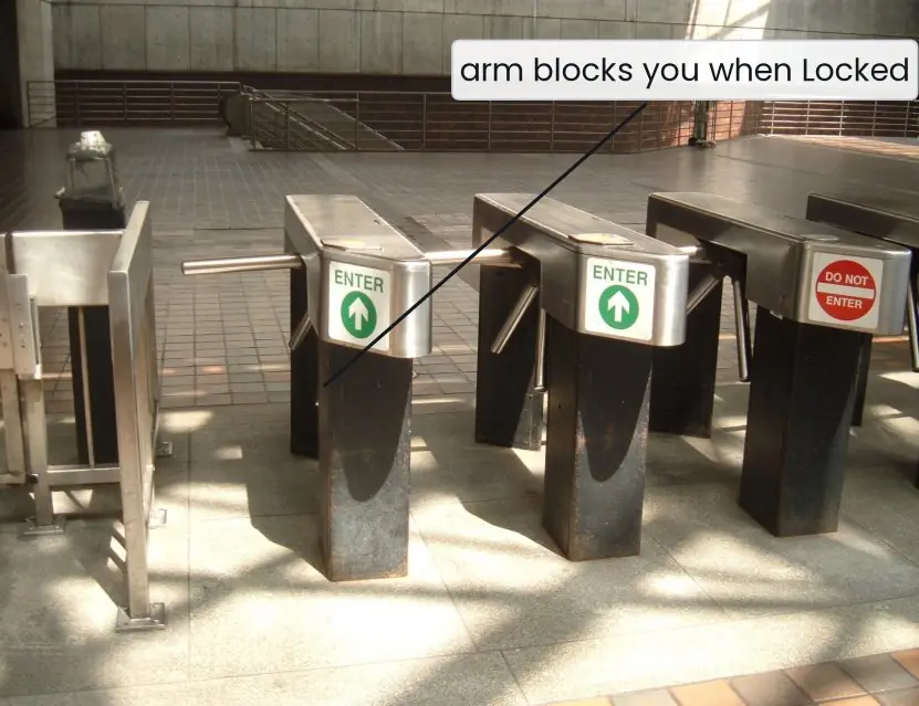
- Turnstiles and ticket gates. The two-state machine of Plate 5.1 lets one person through for each coin or ticket. Stadium gates, parking barriers and airport boarding gates follow the same rule. The same pattern is used for any lock that opens once and then closes again.
- Vending and coin machines. The state records the money inserted so far, and the output releases the item when the total is enough. Each coin is an input event. Ticket machines and prepaid payphones were built this way.
- ATM and keypad locks. An ATM moves through card inserted, PIN entry, amount selection and cash dispensing. A wrong PIN three times sends it to a blocked state. A digital door lock with a secret code is a sequence detector like the 101 detector.
- Pattern matching in software. The compilers of C and Java use a state machine to recognise words and numbers in the source code. Search tools and virus scanners match text using state machines too. The 101 detector of Section 5.4 is the smallest example.
- Communication protocols. TCP, which carries every web page, is defined as a state machine with states such as LISTEN, SYN-SENT and ESTABLISHED. Each packet that arrives is an input. A protocol bug is often a missing arrow in the state diagram.
- Household appliances. A washing machine moves through fill, wash, rinse and spin, and a microwave oven through set, cook and beep. Each step ends by a timer or a sensor. Because the machine has few states, the controller chip is cheap.
Formula and fact sheet
- Moore: z = f(state). Mealy: z = f(state, input).
- n flip-flops → at most 2ⁿ states. Unused codes are don't-cares.
- Partition: group by output, split by next-state blocks, repeat.
- Overlapping "101" detector: D₁ = Q₀x', D₀ = x, z = Q₁x (codes 00/01/10).
- Excitation tables convert state changes into flip-flop inputs.
Chapter summary
- An FSM is a state register plus next-state and output logic.
- Mealy outputs react to the input directly; Moore outputs change only with the state.
- State reduction and sensible assignment shrink the circuit.
- Always check the unused states and test the design with a sample input stream.
Practice
- Differentiate Moore and Mealy machines with one example each.
- How many flip-flops are needed for a machine with 9 states? With 4 states after reduction?
- Reduce the following Moore machine: states A(0): 0→B, 1→A; B(0): 0→A, 1→B; C(1): 0→C, 1→A. State whether any states merge.
- Modify the "101" detector so that overlap is not allowed (after a detection restart from S₀). Give the changed row and re-derive z.
- Design a "11" detector (output 1 when the last two bits are 11, overlapping) with D flip-flops; give D and z.
- For the detector designed in the text, give the output for the input 1 1 0 1 0 1.
- Why must unused states be considered in the design?
Answers and worked solutions
1. Moore: output depends on state only, such as a traffic light controller whose lamp colour is a function of the state. Mealy: output depends on state and input, such as the "101" detector whose output is 1 only while the final 1 is present.
2. 9 states → ⌈log₂ 9⌉ = 4 flip-flops; 4 states → 2.
3. Outputs: A and B give 0, C gives 1. Partition P₁ = {A, B}, {C}. For x = 0: A→B, B→A (both block 1). For x = 1: A→A, B→B (both block 1). No split: A ≡ B. C is alone. The machine reduces to two states, {A, B} and C. (C is also unreachable from A and B, so it could be removed entirely.)
4. From S₂ with x = 1 the output is 1 and the next state is S₀ instead of S₁. The z equation is the same (z = Q₁x); D₀ changes to D₀ = x·Q₁' (the S₂ → S₀ move no longer sets Q₀), while D₁ = Q₀x' is unchanged.
5. States: S₀ (no 1 just seen), S₁ (last bit was 1). S₀: x = 0 → S₀/0, x = 1 → S₁/0. S₁: x = 0 → S₀/0, x = 1 → S₁/1. With Q = 0 for S₀ and 1 for S₁: D = x and z = Qx.
6. The machine goes S₀→S₁ (x=1, z0), S₁→S₁ (x=1, z0), S₁→S₂ (x=0, z0), S₂→S₁ (x=1, z1), S₁→S₂ (x=0, z0), S₂→S₁ (x=1, z1). Output 0 0 0 1 0 1.
7. A glitch, noise or power-up can put the flip-flops in an unused code. If its transitions are not defined, the machine may never return to the intended sequence (lock-out).
Model answers: medium (5 marks) and long (10 marks) questions
Q (5 marks). Distinguish between Mealy and Moore machines with a block diagram description and one example each.
A sequential machine has a memory (flip-flops holding the present state) and combinational logic that computes the next state and the output. The two models differ only in how the output is formed.
| Point | Mealy machine | Moore machine |
|---|---|---|
| Output depends on | present state and present input | present state only |
| Output written on | the transition arc (x/z) | inside the state circle |
| Response | can change in the same clock period as the input | changes only after the clock edge |
| Number of states | usually fewer | usually more (about one extra) |
| Glitches | input noise may reach the output | outputs are clean, synchronous |
| Example | the 101 detector in Figure 5.1 | a traffic-light controller |
In a Mealy machine, Z = g(Q, X) and Q⁺ = f(Q, X); in a Moore machine, Z = g(Q) and Q⁺ = f(Q, X). For example, in the 101 detector of Figure 5.1 the output z = Q₁·x depends on the input, so it is Mealy.
In a Moore version the detector needs a fourth state S3 = "101 seen" with output 1 written inside the state, and the output appears one clock later.
A traffic-light controller (red, green, amber) is naturally Moore, because each light depends only on the state it is in. Moore outputs are glitch-free, while Mealy machines react faster and need fewer flip-flops.
Q (10 marks). Design an overlapping "101" sequence detector as a Mealy machine using D flip-flops. Show the specification, state diagram, state table, assignment, excitation equations and the circuit.
Specification. One serial bit x is applied per clock. The output z must be 1 exactly when the last three bits received are 1, 0, 1. Overlap is allowed, so the stream 10101 gives two detections.
Step 1: states and diagram. Three states record how much of the pattern has been seen: S0 (nothing useful), S1 (last bit 1) and S2 (last two bits 10).
Figure 5.1 shows the arcs: from S0, 0 stays and 1 goes to S1; from S1, 1 stays and 0 goes to S2; from S2, 0 returns to S0 and 1 completes the pattern, so z = 1, and the new 1 may begin another 101 so the next state is S1.
Step 2: state table.
| Present | x = 0: next / z | x = 1: next / z |
|---|---|---|
| S0 | S0 / 0 | S1 / 0 |
| S1 | S2 / 0 | S1 / 0 |
| S2 | S0 / 0 | S1 / 1 |
Step 3: state reduction. Partitioning by output puts S0, S1 and S2 in one block for x = 0 (all give z = 0) but separates S2 for x = 1 (z = 1); the next-state tests then separate S0 from S1, so all three states are distinguishable and no reduction is possible.
Step 4: assignment. Two flip-flops are needed (⌈log₂3⌉ = 2): S0 = 00, S1 = 01, S2 = 10; the code 11 never occurs and is a don't-care.
Step 5: excitation and output equations. For D flip-flops D = Q⁺. D₁ = 1 only when the next state is S2, which happens from S1 with x = 0, so D₁ = Q₀·x'.
D₀ = 1 when the next state is S1, which happens for x = 1 from every state, so D₀ = x. The output is 1 only in S2 with x = 1: z = Q₁·x.
Step 6: circuit. Two D flip-flops with a common clock; one AND gate with inputs Q₀ and x' for D₁; D₀ is connected directly to x; one AND gate with inputs Q₁ and x gives z. The total is two flip-flops, two AND gates and one inverter.
Step 7: check with 10101. S0 → S1 → S2 → S1 (z = 1) → S2 → S1 (z = 1), giving z = 0, 0, 1, 0, 1, which matches the specification.
Conclusion. The procedure (specification, diagram, table, reduction, assignment, equations, circuit) is the same for every sequential design; a counter is the special case in which the next state does not depend on the input.
Q (5 marks). How many flip-flops are needed for a sequential machine? What is state assignment?
A machine with N states needs k flip-flops where 2ᵏ ≥ N, that is k = ⌈log₂ N⌉. Each state gets a different k-bit code, and this choice is called state assignment.
Plate 5.2 lists real examples: a turnstile has 2 states and needs 1 flip-flop, the Mealy 101 detector has 3 states and needs 2, a lift with 3 floors and three movement modes has 9 states and needs 4.
- Count the states from the state diagram after state reduction, because fewer states can mean fewer flip-flops.
- Find k from 2ᵏ ≥ N.
- Assign codes. Any assignment works, but good ones give simpler equations: states that follow one another should differ in few bits.
- Treat the unused codes as don't-cares on the Karnaugh maps; the 101 detector has code 11 unused, which makes the equations shorter.
| Machine | N | k | Unused codes |
|---|---|---|---|
| Turnstile | 2 | 1 | 0 |
| 101 Mealy | 3 | 2 | 1 |
| 101 Moore | 4 | 2 | 0 |
| 3 floors × (idle, up, down) | 9 | 4 | 7 |
Example. For the 101 detector with S₀ = 00, S₁ = 01 and S₂ = 10, the code 11 never occurs, so it is marked X in the next-state maps. Figure 5.2 shows that the Moore version needs one more state (4 instead of 3), although both use 2 flip-flops here.
Q (10 marks). Design a turnstile controller using a D flip-flop. Verify it with a sequence of events.
Introduction. A turnstile (Plate 5.1) has an arm that is Locked until a coin is inserted and then Unlocked until one person pushes through. It is a good example of a sequential machine because its behaviour depends on its history.
We design it as a Moore machine, since the output "arm free" depends only on the state.
Step 1: specification. Inputs: C = coin inserted, P = push on the arm. In each clock cycle at most one of them is 1. Output U = 1 when the arm is free.
Step 2: states. L (Locked, U = 0) and U (Unlocked, U = 1). Two states need k = 1 flip-flop; assign L = 0 and U = 1, so Q is the output itself.
Step 3: state table.
| Present Q | C P | Next Q⁺ | Meaning |
|---|---|---|---|
| 0 (L) | 0 0 | 0 | stay locked |
| 0 (L) | 0 1 | 0 | push is blocked |
| 0 (L) | 1 0 | 1 | coin unlocks |
| 1 (U) | 0 0 | 1 | stay unlocked |
| 1 (U) | 0 1 | 0 | person passes, lock again |
| 1 (U) | 1 0 | 1 | extra coin is wasted |
Step 4: equation. The next state is 1 when a coin arrives or when the gate is unlocked and nobody pushes, so D = Q⁺ = C + Q·P′. The case C = P = 1 never occurs and is a don't-care.
Step 5: circuit. One D flip-flop, one NOT gate (P′), one AND gate (Q·P′) and one OR gate (C + Q·P′). Output U = Q. A clear input sets Q = 0 at power-up so that the gate starts Locked.
Step 6: verification. The events C P P C C P idle P C P give the states 1, 0, 0, 1, 1, 0, 0, 0, 1, 0 (Plate 5.1). Three persons passed, two pushes were blocked and one coin was wasted, which is exactly what the specification demands.
| Part | Choice |
|---|---|
| Machine type | Moore |
| Number of states | 2 |
| Flip-flops | 1 D flip-flop |
| Gates | NOT, AND, OR |
| Equation | D = C + Q·P′ |
Conclusion. The same procedure of specification, states, table, equation, circuit and verification works for a machine of any size. Only the number of flip-flops and the size of the Karnaugh maps grow.
A designer must always check the don't-care input combinations and give the machine a safe starting state.