Unit 4 · 16 teaching hours · 26 min read
Flip-Flops, Counters and Registers
What the syllabus asks for 4
- Latches and flip-flops
- Counters
- Registers
- Applications of flip-flops, counters and registers: eight uses
Combinational circuits forget. To remember a bit, to count, to hold a value while the next one arrives, you need sequential circuits: circuits whose output depends on the present input and on stored state.
The storage element is the flip-flop, and registers and counters are flip-flops wired in useful patterns. Every register in a CPU is such a circuit.
- Latches and the flip-flops SR, JK (and master-slave), D, T: characteristic equations, truth tables, excitation tables.
- Level vs edge triggering, preset/clear, and the race-around condition.
- Asynchronous (ripple) counters, modulus-N counters, ring and Johnson counters.
- Synchronous counters and their design with excitation tables.
- Shift registers (SISO, SIPO, PISO, PIPO), and applications: digital clock, frequency counter.
4.1 Latches and flip-flops
A latch is a level-sensitive bistable element.
The basic SR latch from two cross-coupled NOR gates has inputs Set and Reset: S = 1, R = 0 sets Q = 1; S = 0, R = 1 resets Q = 0; S = R = 0 holds; S = R = 1 is forbidden (both outputs 0, and the result is undefined when both return to 0).
A NAND version has active-low inputs. A gated (clocked) SR latch responds only while the clock enable is high.
A flip-flop changes state only at a clock edge. Terms: Q is the present state, Q⁺ (or Q(t+1)) the next state.
| Type | Inputs | Characteristic equation | Behaviour |
|---|---|---|---|
| SR | S, R | Q⁺ = S + R'Q, with SR = 0 | S = 1 sets, R = 1 resets, 00 holds, 11 not allowed |
| JK | J, K | Q⁺ = JQ' + K'Q | 00 hold, 01 reset, 10 set, 11 toggle |
| D | D | Q⁺ = D | copies D at the clock edge (a one-bit delay) |
| T | T | Q⁺ = T ⊕ Q | T = 0 hold, T = 1 toggle |
JK removes the SR forbidden state by making 11 mean toggle. A D flip-flop is a JK with K = J'. A T flip-flop is a JK with J = K = T, or a D flip-flop with D = T ⊕ Q.
Excitation tables answer "what must the inputs be to go from Q to Q⁺?" and are the key to counter design (X = don't-care):
| Q → Q⁺ | SR: S R | JK: J K | D | T |
|---|---|---|---|---|
| 0 → 0 | 0 X | 0 X | 0 | 0 |
| 0 → 1 | 1 0 | 1 X | 1 | 1 |
| 1 → 0 | 0 1 | X 1 | 0 | 1 |
| 1 → 1 | X 0 | X 0 | 1 | 0 |
Triggering.
Level triggering the output follows the inputs for the whole time the clock is high (or low); the circuit is "transparent".
Edge triggering the inputs are sampled only at the rising (or falling) edge, which makes behaviour predictable. Edge-triggered symbols have a small triangle on the clock input; a bubble means falling-edge or active-low.
Race-around. In a level-triggered JK with J = K = 1 the output toggles repeatedly during the whole clock-high interval whenever that interval exceeds the propagation delay, so the final state is uncertain.
Remedies: master-slave construction (two latches on opposite clock phases, the master takes the input while clock is high and the slave updates when it falls), or edge-triggering, or a very narrow clock pulse.
Asynchronous inputs. Preset (set to 1) and Clear (reset to 0) act immediately, overriding the clock. They initialise counters and registers at power-up.

4.2 Counters
A counter is a sequential circuit that steps through a fixed sequence of states, one per clock pulse. Modulus (MOD) = number of distinct states. n flip-flops give at most 2ⁿ states, so MOD ≤ 2ⁿ.
Asynchronous (ripple) counters
In a ripple counter the clock goes only to the first flip-flop; each following flip-flop is clocked by the output of the previous one.
With T (toggle) flip-flops (JK with J = K = 1) that trigger on the falling edge, Q₀ toggles every clock pulse, Q₁ every two, Q₂ every four: a binary up-counter.
Each stage divides the frequency by two, so an n-stage counter divides by 2ⁿ: a 4-stage ripple counter fed by 1 MHz gives 62.5 kHz at Q₃. Connecting each clock to the complement output Q' counts down.
Counting sequence of a 3-bit up counter (Q₂Q₁Q₀): 000, 001, 010, 011, 100, 101, 110, 111, 000, …
Drawback. The delay accumulates: the last output settles about n × t_pd after the clock.
With t_pd = 20 ns and four stages the output is valid only after 80 ns, so the counter cannot run faster than about 1 / 80 ns = 12.5 MHz, and decoding the state can produce brief false values (glitches) while the ripple passes.
Modulus-N counters by reset. To count 0 … N − 1, use n = ⌈log₂ N⌉ flip-flops and add a NAND gate that detects the binary value N and drives the asynchronous clear (active low) of all flip-flops, forcing the count back to 0 immediately.
| MOD | Flip-flops | Detect and clear at | NAND inputs |
|---|---|---|---|
| 5 | 3 | 101 (5) | Q₂, Q₀ |
| 7 | 3 | 111 (7) | Q₂, Q₁, Q₀ |
| 10 (decade) | 4 | 1010 (10) | Q₃, Q₁ |
| 11 | 4 | 1011 (11) | Q₃, Q₁, Q₀ |
The decade (MOD-10) counter counts 0000 to 1001 and clears on 1010, which is detected by Q₃ = Q₁ = 1 because no earlier state has both set. Its output is BCD, used for one digit of a display (the 7490 chip). The state 1010 exists for only a few nanoseconds.
Ring and Johnson counters
A ring counter is a circular shift register of n D flip-flops with Q of the last fed back to D of the first; preset one stage to 1 and a single 1 circulates.
It has n states with n flip-flops (one-hot) and needs no decoder: 1000 → 0100 → 0010 → 0001 → 1000.
A Johnson (twisted-ring) counter feeds back Q' of the last stage, giving 2n states: for 4 flip-flops 0000 → 1000 → 1100 → 1110 → 1111 → 0111 → 0011 → 0001 → 0000 (8 states). Each state is decoded with a 2-input gate.
Synchronous counters
In a synchronous counter all flip-flops share one clock, so all outputs change together and the speed no longer depends on the number of stages. The price is extra gating.
For a binary up-counter with T flip-flops: T₀ = 1, T₁ = Q₀, T₂ = Q₀Q₁, T₃ = Q₀Q₁Q₂; a stage toggles when all lower bits are 1. The maximum frequency is 1 / (t_pd of one flip-flop + one AND-gate delay).
Design procedure (shown fully in Unit 5): (1) state diagram; (2) number of flip-flops; (3) pick the flip-flop type; (4) write the state table with next states; (5) fill the excitation columns from the excitation table; (6) simplify each input with a K-map (unused states are don't-cares); (7) draw the circuit and check the unused states lead back into the sequence.
Two flip-flops, states Q₁Q₀. Unused state 11 is sent to 00 for self-starting.
| Q₁Q₀ | Next | J₁ K₁ | J₀ K₀ |
|---|---|---|---|
| 00 | 01 | 0 X | 1 X |
| 01 | 10 | 1 X | X 1 |
| 10 | 00 | X 1 | 0 X |
| 11 | 00 | X 1 | X 1 |
K-maps give J₁ = Q₀, K₁ = 1, J₀ = Q₁', K₀ = 1. Check from 01: J₁ = K₁ = 1 toggles Q₁ to 1; J₀ = Q₁' = 1 and K₀ = 1 toggle Q₀ to 0 → 10 ✔.
Applications.
Frequency division and timing a digital clock uses a 32,768 Hz quartz crystal divided by a chain of 15 flip-flops (2¹⁵ = 32,768) to get exactly 1 Hz; the seconds then feed a MOD-10 and MOD-6 counter (00–59), then another MOD-10/MOD-6 pair for minutes, then a MOD-12 or MOD-24 counter for hours, each stage driving a BCD-to-seven-segment decoder.
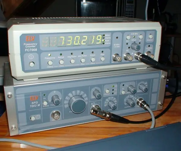
A frequency counter opens an AND gate for exactly one second and counts the input pulses that pass through; the count in that second is the frequency in Hz. Counters are also used as address generators, event counters and in timers.


4.3 Registers
A register is a group of flip-flops holding a binary word, all sharing one clock; an n-bit register stores n bits. A shift register also moves the bits one position on each clock pulse. Four modes:
| Mode | Input | Output | Clock pulses to load 4 bits |
|---|---|---|---|
| SISO serial-in, serial-out | one bit at a time | one bit at a time | 4 to load, 4 more to read out: a delay line |
| SIPO serial-in, parallel-out | serial | all bits at once | 4 (serial-to-parallel conversion, e.g. receiver) |
| PISO parallel-in, serial-out | all bits at once (load line) | serial | 1 to load, 4 to send (parallel-to-serial, transmitter) |
| PIPO parallel-in, parallel-out | all bits | all bits | 1 (a storage register) |
Built from D flip-flops with each Q wired to the next D. Loading 1011 serially (first bit 1 entered first): after four clocks the register holds Q₃Q₂Q₁Q₀ = 1011 with the first bit at the far end.
Right shift moves bits towards the LSB end (divides an unsigned number by 2); left shift doubles it.
A universal shift register (74194) has a mode control to do hold, shift left, shift right and parallel load, and is built with a 4-to-1 MUX in front of every flip-flop.
Registers are used for temporary storage in the CPU, serial communication (UART), delay lines, sequence generation (ring and Johnson counters are shift registers with feedback), and arithmetic (shift-and-add multiplication).



4.4 Applications of flip-flops, counters and registers: eight uses
- Memory cells. A flip-flop stores one bit as long as power is on. Registers inside a CPU and the cache memory are arrays of such cells. A 32-bit register is simply 32 flip-flops sharing one clock.
- Frequency division. A T flip-flop halves the clock frequency, so n stages divide by 2ⁿ. A 32.768 kHz watch crystal passes through 15 stages to give exactly 1 Hz. The same idea gives slower clocks inside microcontrollers.
- Digital clocks and timers. Counters count seconds, minutes and hours, and a decoder drives the display. The token board at a bank counter and the timer on a microwave oven are examples. A MOD-60 counter resets after 59.
- Event and frequency counters. A counter can count pulses from a sensor in a fixed time. A factory in Hetauda counting bottles on a belt, or a meter measuring the speed of a motor, works in this way. The count is the reading.
- Serial-to-parallel conversion. A shift register collects bits one by one from a wire and then offers them all together. USB, UART and Ethernet ports do this at high speed. Parallel-to-serial conversion works in the opposite direction.
- Delay lines and pipelines. A shift register delays a signal by a known number of clock periods. Pipelined CPUs put registers between stages to hold each instruction while the next one starts. This raises the speed of the whole processor.
- Ring and Johnson counters for control. A ring counter keeps one flip-flop at 1 and moves it around. It gives timing pulses that switch traffic lights or step a stepper motor in sequence. Johnson counters give 2n states from n flip-flops.
- Synchronisation and debouncing. A D flip-flop samples an input at the clock edge, which turns a noisy or asynchronous signal into a clean one. Keyboard keys and push buttons need this because their contacts bounce. It also protects the CPU from signals that arrive at random times.
4.4.1 Eight places where Nepali users meet flip-flops and counters
- Digital watch and clock. A 32.768 kHz crystal feeds a chain of 15 flip-flops that halves the frequency to exactly 1 Hz. More counters turn seconds into minutes and hours. Every wristwatch and wall clock sold in Kathmandu works this way.
- Electricity meter. The digital meters of Nepal Electricity Authority count pulses from the measuring chip, and each group of pulses is one unit of energy. Counters and registers hold the running reading that you see on the display. The register keeps the value even during a short power cut.
- Bank token display. The counter at a bank queue is an up counter with a decoder for a seven-segment display. When the clerk presses the button, the counter adds one. Reset puts it back to zero at the start of the day.
- Traffic lights. A ring-type counter steps through green, yellow and red, and a timer sets how long each lasts. Junctions such as Ratna Park and Kalanki use controllers built on the same idea. The signals change in a fixed order without any person.
- Lifts. A register remembers which floor buttons were pressed and which floor the car has reached. The control logic compares them and starts or stops the motor. The memory of every press is stored in flip-flops.
- Mobile phones and computers. The CPU registers, cache and RAM cells are arrays of flip-flop-like cells. A 64-bit processor has dozens of 64-bit registers made of such cells. All of them are written at the clock edge, billions of times per second.
- Keyboards and buttons. A D flip-flop samples the key line on the clock and removes the jitter of a bouncing contact. Without it one key press could appear as several letters. USB keyboards and ATM keypads rely on this.
- Serial ports and Wi-Fi. Shift registers turn the serial bit stream of USB, UART and Ethernet into bytes, and bytes back into a stream (Figure 4.3). Routers and modems do this millions of times each second. Without it computers could not talk over a single wire or antenna.
Formula and fact sheet
- SR: Q⁺ = S + R'Q (SR = 0). JK: Q⁺ = JQ' + K'Q. D: Q⁺ = D. T: Q⁺ = T ⊕ Q.
- Excitation: JK 0→1 is "1X", 1→0 is "X1"; T = Q ⊕ Q⁺; D = Q⁺.
- n flip-flops: MOD ≤ 2ⁿ; ripple divides frequency by 2ⁿ.
- Ripple settling time ≈ n × t_pd; f_max ≈ 1 / (n × t_pd).
- Ring: n states; Johnson: 2n states.
- Reset to make MOD-N: NAND the outputs that are 1 in the binary value of N.
- Digital clock: 32,768 Hz / 2¹⁵ = 1 Hz.
Chapter summary
- Flip-flops store one bit and change on a clock edge; JK toggles on 11, D delays, T toggles.
- Excitation tables turn a wanted state change into flip-flop inputs.
- Ripple counters are simple and slow; synchronous counters are fast and need design.
- Counters count and divide frequency; registers store and shift words.
Practice
- Write the characteristic equation and truth table of the JK flip-flop. How does it differ from SR?
- What is the race-around condition and how is it removed?
- Derive the T flip-flop from a JK flip-flop; derive a D flip-flop from a JK.
- A 4-bit ripple counter uses flip-flops with t_pd = 25 ns. Find the maximum clock frequency (counter-settling basis) and the output frequency at Q₃ for a 4 MHz input.
- Draw (describe) a MOD-10 ripple counter and give the state at which it is cleared.
- What is the counting sequence of a 3-bit down counter?
- List the 8 states of a 4-bit Johnson counter, starting at 0000.
- Design a synchronous 2-bit counter that goes 00 → 01 → 11 → 10 → 00 with D flip-flops.
- A 4-bit PISO register is clocked at 1 kHz. How long does it take to send out one loaded word?
- How many flip-flops are needed for a MOD-60 counter, and how would you build it from decade counters?
Answers and worked solutions
1. Q⁺ = JQ' + K'Q. J K = 00 → Q; 01 → 0; 10 → 1; 11 → Q'. SR has the forbidden input 11; JK uses it to toggle.
2. With J = K = 1 on a level-triggered clock, the output toggles repeatedly while the clock stays high (longer than t_pd), leaving the final state uncertain. Use a master-slave or edge-triggered flip-flop.
3. Tie J and K together: T flip-flop, Q⁺ = TQ' + T'Q = T ⊕ Q. For D: J = D, K = D', so Q⁺ = DQ' + DQ = D.
4. Settling time 4 × 25 = 100 ns → f_max ≈ 10 MHz. Q₃ output = 4 MHz / 16 = 250 kHz.
5. Four toggle flip-flops in ripple; NAND(Q₃, Q₁) drives the active-low clear; it clears at 1010 (decimal 10), so the stable states are 0000–1001.
6. 111, 110, 101, 100, 011, 010, 001, 000, then 111 again.
7. 0000, 1000, 1100, 1110, 1111, 0111, 0011, 0001.
8. The next Q₁ is 0, 1, 1, 0 for states 00, 01, 11, 10, so D₁ = Q₀. The next Q₀ is 1, 1, 0, 0, so D₀ = Q₁'. Check: 00 → 01 → 11 → 10 → 00 ✔.
9. At 1 kHz one clock period is 1 ms. One pulse loads the word and then four periods shift the four bits out, so the word is transmitted in 4 ms after a 1 ms load (5 ms in all).
10. A single binary counter for 60 states needs 6 flip-flops (2⁶ = 64 ≥ 60). The practical BCD build is a MOD-10 counter (4 flip-flops) cascaded with a MOD-6 counter (3 flip-flops), 7 in total: the MOD-10 carries into the MOD-6 every ten pulses, and both give BCD outputs for a two-digit display counting 00–59.
Model answers: medium (5 marks) and long (10 marks) questions
Q (5 marks). Explain the JK flip-flop with its truth table and characteristic equation. How does it avoid the invalid state of the SR flip-flop? What is the race-around condition?
A JK flip-flop is a clocked bistable circuit with two inputs J (set) and K (reset) and outputs Q and Q'. It is the most flexible flip-flop because every input combination has a defined result.
| J | K | Q⁺ (next state) | Action |
|---|---|---|---|
| 0 | 0 | Q | hold |
| 0 | 1 | 0 | reset |
| 1 | 0 | 1 | set |
| 1 | 1 | Q' | toggle |
Characteristic equation: Q⁺ = JQ' + K'Q. In an SR flip-flop the input S = R = 1 is forbidden, because both outputs would try to go to 0 and the final state is unpredictable.
In the JK flip-flop the outputs are fed back to the input gates so that the combination J = K = 1 simply toggles the output. The invalid state is therefore turned into a useful function.
Race-around. In a level-triggered JK flip-flop with J = K = 1, the output toggles and, since the clock is still high, the new output feeds back and toggles it again, many times during one pulse; the final state is uncertain.
It is cured by (1) using edge triggering, (2) a master–slave construction, or (3) making the clock pulse shorter than the propagation delay. With J = K = T the JK becomes a T flip-flop, and with K = J' it becomes a D flip-flop.
Q (10 marks). Describe the 3-bit asynchronous (ripple) counter with its timing diagram. Compare asynchronous and synchronous counters.
Introduction. A counter is a sequential circuit built from flip-flops that goes through a fixed sequence of states when clock pulses arrive.
A counter with n flip-flops has at most 2ⁿ states; the number of states it uses is its modulus (MOD). A 3-bit binary counter is MOD-8.
Construction. Use three T flip-flops (JK with J = K = 1), as in Figure 4.1. The external clock drives only the first stage. The output Q0 of the first stage is the clock of the second, and Q1 is the clock of the third.
Each flip-flop toggles on the falling edge of its own clock input.
Operation. Starting from 000: the first falling edge of CLK makes Q0 = 1 (001). The second makes Q0 = 0, and that falling edge toggles Q1, giving 010. The third gives 011, and the fourth takes Q0 and Q1 to 0 and toggles Q2, giving 100.
The count continues to 111 and then returns to 000 on the eighth edge. Frequencies: Q0 = f/2, Q1 = f/4 and Q2 = f/8, so a counter is also a divider.
Ripple delay and its limit. Each stage waits for the previous one, so the delay of an n-bit ripple counter is n × t_pd.
For a 3-stage counter with t_pd = 10 ns the final output settles after 30 ns, and the maximum clock is limited to about 1 / (n × t_pd).
During the ripple the outputs pass through false states (for example 011 → 010 → 000 → 100), which may cause glitches in a decoder.
Other counters. Down counter: use Q' to clock the next stage. MOD-N counter: detect state N with a NAND gate and use it to clear all flip-flops asynchronously; for MOD-6 detect 110 (Q2 Q1) and clear.
| Point | Asynchronous (ripple) | Synchronous |
|---|---|---|
| Clock | only the first stage | all stages together |
| Delay | n × t_pd | one t_pd |
| Speed | slow | fast |
| Hardware | simplest | extra AND gates |
| False states | yes | no |
| Design | trivial | uses excitation tables |
| Use | frequency dividers | CPUs, high-speed counters |
Conclusion. The ripple counter is simple, cheap and good as a frequency divider; when speed matters, a synchronous counter is used because all flip-flops change at the same instant.
Q (5 marks). What is the race-around condition in a JK flip-flop? How is it removed?
In a level-triggered JK flip-flop with J = K = 1 the output toggles each time the signal has travelled through the gates, that is once per propagation delay t_pd, for as long as the clock is high.
If the clock-high time t_w is longer than t_pd, the output races around: it toggles many times and the final state cannot be predicted. Plate 4.1 simulates a flip-flop with t_pd = 10 ns:
| Clock pulse | Toggles | Final Q |
|---|---|---|
| 5 ns | 0 | 0 (pulse missed) |
| 15 ns | 1 | 1 |
| 25 ns | 2 | 0 |
| 35 ns | 3 | 1 |
| 50 ns | 5 | 1 |
Remedies
- Edge triggering: the flip-flop reads its inputs only at the rising or falling edge, so it toggles once per clock whatever the pulse width.
- Master-slave construction: two latches in series; the master follows the inputs while the clock is high, the slave copies it only when the clock falls, so the output cannot change twice in one pulse.
- Narrow clock pulse: make t_w smaller than t_pd. It is unreliable because the delay varies with temperature, so it is not used.
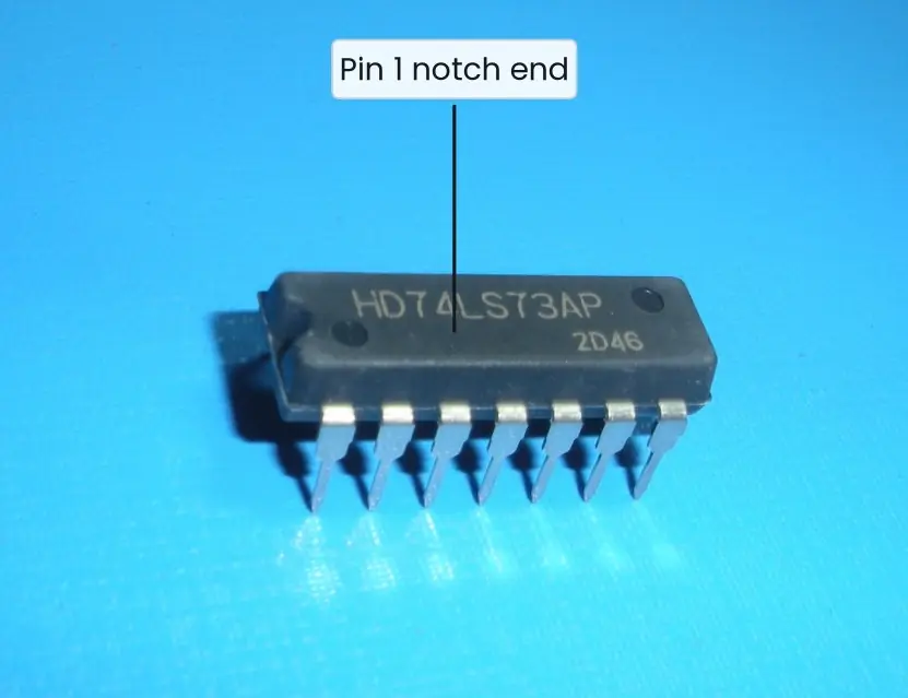
Example. The 74LS73 of Plate 4.1 is a JK flip-flop that changes only at the falling clock edge, so J = K = 1 gives a clean divide-by-2.
Q (5 marks). Design a MOD-6 asynchronous (ripple) counter.
A MOD-6 counter counts 0 to 5 and returns to 0, so it needs 3 flip-flops (2³ = 8 ≥ 6). Use three T (or JK with J = K = 1) flip-flops with negative-edge clock, each clocked by the previous output, which gives a free-running MOD-8 counter.
- Count sequence: 000, 001, 010, 011, 100, 101, then 110 would come next.
- Detect the first unwanted state 110: connect Q2 and Q1 to a NAND gate. Its output goes low only when Q2 = Q1 = 1, which is first true at 110 (state 6).
- Clear: connect the NAND output to the active-low Clear inputs of all three flip-flops, so the counter returns to 000 at once.
| Clock pulse | Q2 Q1 Q0 |
|---|---|
| 0 | 000 |
| 1 | 001 |
| 2 | 010 |
| 3 | 011 |
| 4 | 100 |
| 5 | 101 |
| 6 | 110 → cleared → 000 |
State 110 lasts only a few nanoseconds, so it is not seen as a count. Frequency division: the Q2 output has frequency f / 6, so a 6 kHz clock gives 1 kHz at Q2 (the duty cycle is one-third, not 50%).
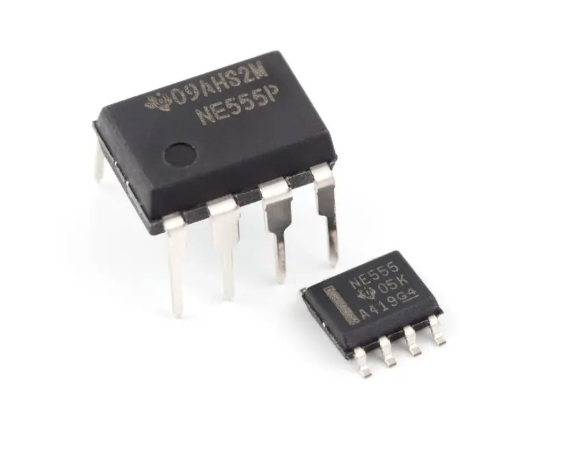
Plate 4.2 shows that the settling time grows with the number of stages, which is the main limit of ripple counters.
Q (10 marks). Explain the types of shift register and their applications.
Introduction. A shift register is a group of flip-flops connected in a chain, all with the same clock, in which the stored bits move one place at every clock pulse.
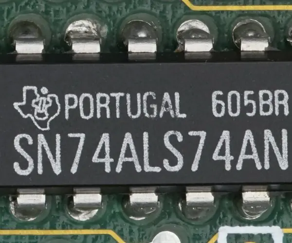
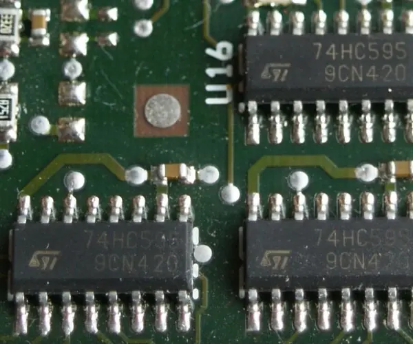
An n-bit register is made of n flip-flops, usually D type, and stores an n-bit word (Plate 4.3 shows real shift-register chips).
Types
- Serial-in serial-out (SISO): data enter and leave one bit at a time; it works as a delay line. A 4-bit SISO delays a signal by 4 clock periods.
- Serial-in parallel-out (SIPO): bits enter one by one and all outputs are read together. Figure 4.3 shows the letter N (01001110) collected in 8 clocks. Used in the receiver of a UART.
- Parallel-in serial-out (PISO): a load line puts all bits in at once, then they are sent out one by one. Used in the transmitter of a serial port and in keyboard scanning.
- Parallel-in parallel-out (PIPO): all bits load and leave together at one clock; it is a plain storage register as inside a CPU.
- Bidirectional register: a direction control makes the bits move left or right. Shifting left multiplies a binary number by 2 and shifting right divides it by 2.
- Universal shift register: has mode inputs to choose hold, shift left, shift right or parallel load; the 74194 is the standard chip.
- Ring counter: the last output is fed back to the first input, so one 1 circulates (MOD-n with n flip-flops).
- Johnson counter: the inverted last output is fed back; it gives MOD-2n, so four flip-flops give 8 states (Figure 4.4).
| Type | Input | Output | Typical use |
|---|---|---|---|
| SISO | serial | serial | delay line |
| SIPO | serial | parallel | UART receiver, 74HC595 |
| PISO | parallel | serial | UART transmitter |
| PIPO | parallel | parallel | CPU register |
Applications. Serial-to-parallel and parallel-to-serial conversion, time delay, multiplying and dividing by 2, ring and Johnson counters for control timing, and extra output pins for a microcontroller through a 74HC595.
Conclusion. Shift registers are the simplest sequential circuits and the key link between serial communication and parallel processing. By choosing the way data enter and leave, one chain of flip-flops can act as storage, delay line, converter or counter.