Unit 2 · 6 teaching hours · 17 min read
Database Design, Architecture and Model
What the syllabus asks for 7
- The design process and the view of data
- Structure of a DBMS and three-level architecture
- Database languages
- Data models
- The entity-relationship model
- Converting an E-R diagram to tables
- Seeing the ideas: views, models and diagrams
This unit shows how a database is designed before any table is created: the architecture that hides storage details, the languages used, the data models, and above all the entity-relationship (E-R) model.
- The design process, three-level architecture and data independence.
- DDL, DML and QBE; the main data models.
- E-R diagrams: entities, attributes, relationships, cardinality, weak entities, generalisation, aggregation.
- Converting an E-R diagram into tables.
2.1 The design process and the view of data
Design proceeds in stages: (1) requirements gathering; (2) conceptual design (E-R diagram, independent of any DBMS); (3) logical design (convert to relations of the chosen model, normalise); (4) physical design (file organisation, indexes).
A schema is the description of the database (rarely changes); an instance is the data in it at one moment (changes constantly).
2.2 Structure of a DBMS and three-level architecture
Components: the DDL compiler, query processor (parser, optimiser, evaluator), storage manager (buffer, file and index manager, transaction and authorisation managers), and the data dictionary.
The ANSI/SPARC three-level architecture separates:
| Level | Describes | Who sees it |
|---|---|---|
| External (view) | the part of the database a user group needs | end users, programmers |
| Conceptual (logical) | the whole database: entities, relations, constraints | DBA, designers |
| Internal (physical) | files, indexes, blocks, compression | DBMS, DBA |
Data independence: physical independence means changing the internal level (adding an index) does not change the conceptual schema or programs; logical independence means changing the conceptual schema (adding a column) does not break external views.
Mappings between levels make this possible.
2.3 Database languages
| Language | Purpose | Statements |
|---|---|---|
| DDL (data definition) | define and change schema | CREATE, ALTER, DROP, TRUNCATE |
| DML (data manipulation) | query and change data | SELECT, INSERT, UPDATE, DELETE |
| DCL (data control) | permissions | GRANT, REVOKE |
| TCL (transaction control) | transactions | COMMIT, ROLLBACK, SAVEPOINT |
DML is procedural (say how) or declarative/non-procedural (say what; SQL). Query By Example (QBE) is a graphical language where the user fills in skeleton tables with example values, and the system turns them into a query.
Example in a Student skeleton, putting P. under name and >80 under marks means "print names of students with marks over 80".
2.4 Data models
| Model | Idea |
|---|---|
| Hierarchical | records in a tree; each child has one parent (IBM IMS) |
| Network | records in a graph; a child may have many parents (CODASYL) |
| Relational | data in tables (relations) linked by values; the dominant model (Unit 3) |
| Entity-relationship | entities and relationships for conceptual design |
| Object-based | objects with attributes, methods and inheritance; object-relational systems add this to tables |
2.5 The entity-relationship model
- Entity: a distinguishable thing (a student). Entity set: all entities of one type. Drawn as a rectangle.
- Attribute: a property, drawn as an ellipse. Kinds: simple/composite (name = first + last), single/multi-valued (phone numbers, double ellipse), stored/derived (age from date of birth, dashed ellipse), key attribute (underlined).
- Relationship: an association among entities, drawn as a diamond. Degree = number of entity sets (binary is most common).
- Cardinality ratio: 1:1, 1:N, N:1, M:N. Participation: total (every entity must take part; double line) or partial.
- Strong entity has its own key. Weak entity has none: it depends on an owner entity through an identifying relationship (double diamond) and is identified by the owner's key plus its own partial key. Example:
DependentofEmployee.
Entities: Department(dept_id, name), Student(sid, name, phone*, dob), Course(cid, title, credits).
Relationships: Department offers Course (1:N, total on Course); Department has Student (1:N); Student enrols in Course (M:N, with attribute marks, because the mark belongs to the pair, not to either alone).
Generalisation, specialisation, aggregation
- Specialisation (top-down): split an entity set into sub-groups with extra attributes:
Person→Student,Teacher(an ISA triangle). Generalisation is the same in reverse (bottom-up): combine similar entity sets. Constraints: disjoint or overlapping; total or partial. Subclasses inherit the parent's attributes. - Aggregation treats a relationship (with its entities) as a higher-level entity so it can take part in another relationship. Example:
Employee works-on Projectis aggregated, then Manager monitors that whole assignment.
2.6 Converting an E-R diagram to tables
| E-R construct | Table(s) |
|---|---|
| Strong entity | one table; simple attributes become columns; composite attributes are flattened; key becomes the primary key |
| Multi-valued attribute | separate table (owner key, value); the pair is the key |
| 1:1 relationship | add the key of one side as a foreign key to the other (prefer the total side) |
| 1:N | add the key of the N side's partner (the "1" side's key) as a foreign key in the N side's table |
| M:N | new table with both keys (as a composite primary key) plus relationship attributes |
| Weak entity | table with owner's key + partial key as primary key |
| Specialisation | table per subclass with the parent's key (or one table with a type column) |
department(dept_id PK, name) · student(sid PK, name, dob, dept_id FK) · student_phone(sid FK, phone, PK(sid, phone)) · course(cid PK, title, credits, dept_id FK) · enrollment(sid FK, cid FK, marks, PK(sid, cid)).
The M:N relationship became enrollment; the 1:N relationships became foreign keys; the multi-valued phone got its own table.
2.7 Seeing the ideas: views, models and diagrams
A library card catalogue is the best everyday picture of a database view. Every book has one physical copy on a shelf but several cards in the cabinet: one filed under the author, one under the title and one under the subject.
The reader sees a different arrangement of the same facts, which is exactly what the external level of a DBMS offers.
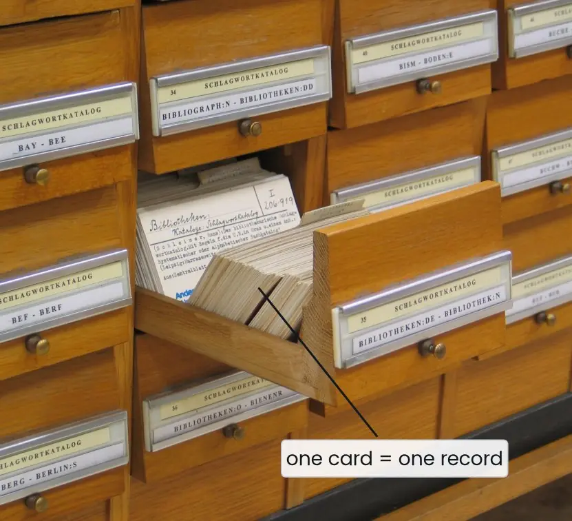


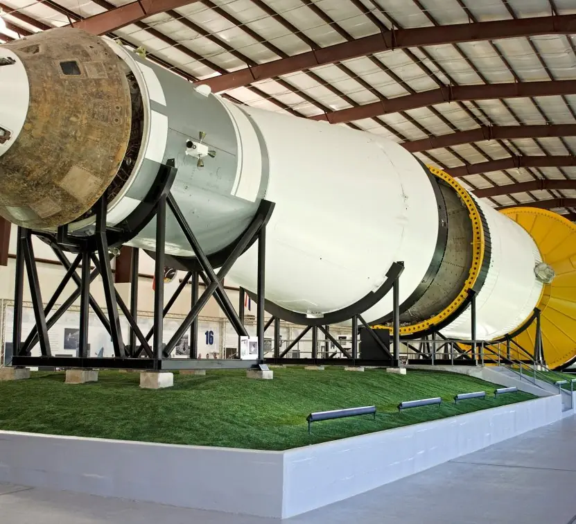
The hierarchical model is easiest to understand in something you can photograph.
When IBM, North American Rockwell and Caterpillar built the Information Management System (IMS) in the 1960s, one of the first jobs was the bill of materials of the Apollo rockets: a rocket is made of stages, a stage of engines and tanks.
Every part has exactly one parent, so the data forms a tree. The plate below keeps that bill of materials in a single table and asks a real PostgreSQL server how many parts sit at each level.

2.7.1 Eight advantages of the three-level architecture and data independence
- Different users get different views. The library clerk does not need to see marks and the exam officer does not need to see fines. Each external view shows only the columns and rows that a group needs. This keeps screens simple and reports focused.
- Security improves. A view can hide sensitive columns such as salary or password. Users are given permission on the view and never on the base table. A Nepali bank can therefore let a teller see an account balance but not the loan file.
- Physical changes do not break programs. If the DBA adds an index or moves the table to a faster disk, only the internal schema changes. The mapping to the conceptual level absorbs the change. This property is called physical data independence.
- Logical changes can be absorbed. When a new column such as email is added to Student, existing views and programs keep working because they never mention it. Logical data independence is harder to achieve than physical independence, but views make it possible in many cases. Older applications continue to run during an upgrade.
- Lower maintenance cost. Programs depend on a stable logical description, not on file layouts. Rewriting hundreds of programs after every storage change is avoided. Colleges that upgrade their server do not have to rewrite their result software.
- One agreed description of the data. The conceptual schema is the single, shared definition of every table, key and constraint. Everyone in the organisation, from designer to programmer, refers to the same document. Misunderstandings about what a column means become rare.
- Easier design and teaching. Designers can think logically first (E-R diagram, tables) and decide on storage later. A student of Tribhuvan University can learn SQL without knowing anything about disk blocks. The levels divide a complex job into smaller parts.
- Better performance tuning. The DBA can improve speed at the internal level, with indexes, clustering or partitioning, while users keep the same queries. A slow monthly report can be made faster overnight without telling anyone. Tuning and application development proceed independently.
Formula and fact sheet
- Three levels: external, conceptual, internal; two independences: logical and physical.
- E-R symbols: rectangle (entity), double rectangle (weak), ellipse (attribute), diamond (relationship).
- Tables from E-R: M:N → new table; 1:N → foreign key on the N side; multi-valued → own table.
Chapter summary
- Design goes requirements → E-R → relations → physical.
- The three-level architecture gives data independence.
- E-R models entities, attributes, relationships, cardinality and participation; extended E-R adds ISA and aggregation.
- Conversion rules turn the diagram into relational tables mechanically.
Practice
- Explain the three-level architecture and the two kinds of data independence.
- Differentiate DDL, DML, DCL and TCL with statements.
- Define weak entity with an example.
- Draw an E-R diagram (describe entities, keys, cardinalities) for a library: books, members, loans.
- Convert it to tables.
- What are generalisation and aggregation?
- Distinguish schema and instance.
Answers and worked solutions
1. External (user views), conceptual (whole logical schema), internal (storage). Physical independence: storage changes without affecting the conceptual schema; logical independence: conceptual changes without affecting external views/programs.
2. DDL defines (CREATE, ALTER, DROP); DML manipulates (SELECT, INSERT, UPDATE, DELETE); DCL controls access (GRANT, REVOKE); TCL controls transactions (COMMIT, ROLLBACK).
3. An entity without its own key, identified through an owner: Dependent(name, age) of Employee.
4. Entities: Book(isbn, title), Member(mid, name), Loan as relationship Member borrows Book (M:N, attributes issue_date, due_date, return_date).
5. book(isbn PK, title), member(mid PK, name), loan(mid FK, isbn FK, issue_date, due_date, return_date, PK(mid, isbn, issue_date)): the date joins the key so the same member can borrow the same book twice.
6. Generalisation: combine entity sets with common features into a super-class; aggregation: treat a relationship as an entity to relate it to others.
7. Schema: the structure (rarely changes). Instance: the data at one moment.
Model answers (5 and 10 marks)
Q1 (5 marks). Explain the database languages DDL, DML, DCL and TCL with examples.
Introduction. A DBMS provides several sub-languages, all usually parts of SQL, so that users can define data, use it, protect it and control transactions.
- DDL (Data Definition Language). It defines and changes the structure, that is, the schema. Commands are
CREATE,ALTER,DROPandTRUNCATE. For exampleCREATE TABLE student(sid INT PRIMARY KEY, name VARCHAR(40));creates a table. The result is stored as metadata in the data dictionary. - DML (Data Manipulation Language). It retrieves and changes the data inside tables with
SELECT,INSERT,UPDATEandDELETE. DML is either procedural, where the user says how to get the data, or declarative (non-procedural), where the user says only what is wanted, as SQL does. A query such asSELECT name FROM student WHERE sid = 7;is declarative DML. - DCL (Data Control Language). It controls access with
GRANTandREVOKE. For exampleGRANT SELECT ON student TO clerk;lets the user clerk read the table and nothing more. - TCL (Transaction Control Language). It controls transactions with
COMMIT,ROLLBACKandSAVEPOINT. After a group of updates,COMMITmakes them permanent andROLLBACKundoes them.
Example. In a college system the DBA uses DDL to create the tables, the clerk uses DML to enter marks, the DBA uses DCL to limit the clerk and TCL ensures that a half-entered mark sheet is not saved.
Conclusion. Together the four groups cover the whole life of data from definition to safe use.
Q2 (5 marks). What is data independence? Explain the three-level architecture of a DBMS with a diagram.
Introduction. Data independence is the ability to change the schema at one level without changing the schema at the next higher level. The three-level (ANSI-SPARC) architecture of Figure 2.1 makes this possible.
- External level (view level). It describes the part of the database that one user group sees, for example the library view with sid and name. There can be many external views.
- Conceptual level. It describes the whole database logically: entities, attributes, relationships, keys and constraints, without any storage detail. There is only one conceptual schema.
- Internal level (physical level). It describes how the data are stored: file organisation, indexes, block size and compression.
- Mappings. The external/conceptual mapping and the conceptual/internal mapping translate a request from one level to the next.
- Physical data independence. The storage can be reorganised, for example by adding an index, without altering the conceptual schema or programs.
- Logical data independence. The conceptual schema can be extended, for example by adding a column, without altering existing views or programs.
Example. If a college adds an email column to Student, the exam view and its programs continue to work unchanged.
Conclusion. The three levels separate what users see, what the database means and how it is stored, which reduces maintenance cost.
Q3 (10 marks). Explain the entity-relationship model. Draw an E-R diagram for a college and convert it into tables.
Introduction. The entity-relationship (E-R) model, proposed by Peter Chen in 1976, describes the real world as entities, attributes and relationships.
An E-R diagram is a plan that designers and users can discuss before any table is created. Figure 2.2 shows the college example.
Components.
- Entity and entity set. An entity is a distinguishable object such as one student; all students form an entity set, drawn as a rectangle.
- Attributes. Properties drawn as ellipses: simple or composite, single-valued or multi-valued (double ellipse), stored or derived (dashed ellipse), and the key attribute, which is underlined.
- Relationship. An association among entity sets, drawn as a diamond. Its degree is the number of entity sets joined; binary relationships are the most common.
- Cardinality. One-to-one (1:1), one-to-many (1:N), many-to-one and many-to-many (M:N).
- Participation. Total (every entity takes part, a double line) or partial.
- Strong and weak entities. A weak entity such as Dependent has no key of its own and depends on an owner through an identifying relationship (double diamond).
- Specialisation, generalisation and aggregation extend the model with sub-classes and with relationships treated as entities (Figure 2.4).
The college diagram. Department offers Course (1:N), Department has Student (1:N), and Student enrols in Course (M:N) with the attribute marks.
Conversion to tables. Each strong entity becomes a table, 1:N relationships become a foreign key on the N side, and the M:N relationship becomes a new table.
| Table | Columns | Keys |
|---|---|---|
| department | dept_id, name | PK dept_id |
| student | sid, name, dob, dept_id | PK sid; FK dept_id |
| student_phone | sid, phone | PK (sid, phone); FK sid |
| course | cid, title, credits, dept_id | PK cid; FK dept_id |
| enrollment | sid, cid, marks | PK (sid, cid); FK sid, FK cid |
Conclusion. The E-R model lets designers capture requirements in a simple picture, and the mapping rules turn that picture into correct relational tables with the right keys.